BWR type nuclear power generator and construction method

A nuclear energy and power station technology, applied in the field of power stations, can solve problems such as difficult standardized design, large amount of work and construction period, and economic problems, and achieve the effect of low cost and large size

Inactive Publication Date: 2002-05-29
KK TOSHIBA
View PDF0 Cites 7 Cited by
  • Summary
  • Abstract
  • Description
  • Claims
  • Application Information

AI Technical Summary

Problems solved by technology

[0030] Moreover, when using the nuclear reactor container 422 as the upper part of the pressure suppression pool, and using the existing forced circulation nuclear reactor for the nuclear reactor pressure vessel 423, the height of the nuclear reactor pressure vessel 423 is about 20 m. The upper part of the container 423 is led out, led back to the bottom of the pressure suppression pool 433, and led to the turbine, so there is an economical disadvantage of increasing the number of piping materials and dry well space
[0031] Furthermore, in the existing buildings of boiling water type nuclear power plants, generally, equipment with different seismic levels of the nuclear reactor building and the turbine building are accommodated, so separate seismic design and construction are required since they are carried out in separate buildings. design, and, because of the increase in plane space, there are economical problems
Furthermore, it is difficult to achieve a standardized design because the design criteria (specifications, seismic conditions, etc.) of nuclear power plant buildings are different at each construction site.
Furthermore, there is a problem that the work volume and construction period of the nuclear power plant building construction become very large

Method used


Image

  • BWR type nuclear power generator and construction method
  • BWR type nuclear power generator and construction method
  • BWR type nuclear power generator and construction method

Examples


Embodiment Construction

[0091] Refer below Figure 1 to Figure 14 An embodiment of the boiling water type atomic power plant according to the present invention will be described.

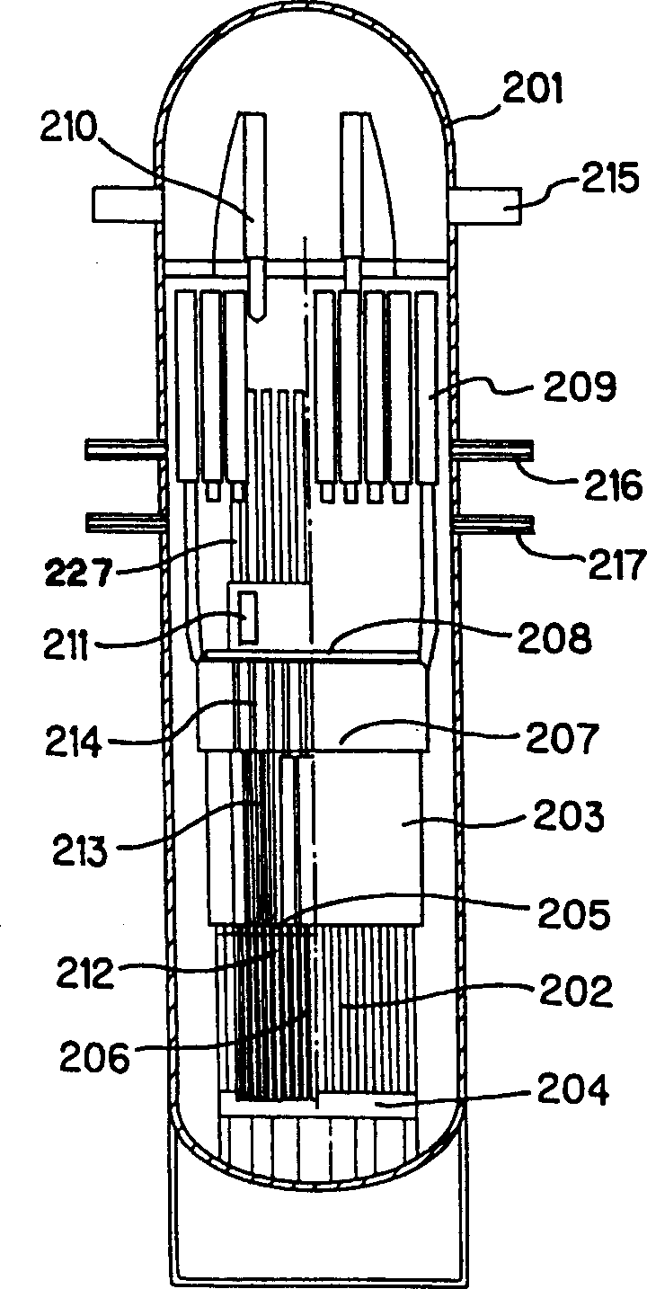
[0092] figure 1 It is a cross-sectional view showing a schematic configuration of a nuclear reactor pressure vessel. Such as figure 1 As shown, in this embodiment, a reactor core 202 is provided at the lowest end position in the nuclear reactor pressure vessel 201 . That is, a reactor core support plate 204 is provided near the bottom of the nuclear reactor pressure vessel 201, and a plurality of fuel assemblies 206 arranged in a square grid are vertically supported on the reactor core support plate 204. The upper ends of the fuel assemblies 206 are formed by The upper grid plate 205 is fixed, thereby constituting the reactor core 202 .

[0093] The control rods 212 are cross-shaped control rods, are regularly arranged corresponding to the four fuel assemblies 206 , and are inserted from the upper part of the reactor...


PUM


Abstract

The present invention provides a boiling water reactor nuclear power plant in which a reactor core support plate, upper grid plate, and a reactor core consisting of fuel assemblies supported by these plates are provided in the inner base portion of a nuclear reactor pressure vessel. Control rod guide tubes and a reactor core shroud are positioned over the upper grid plate, and a control rod drive mechanism is provided further above same, whereby the control rods can be inserted from above the reactor core, and natural circulation of cooling water inside the reactor can be achieved by means of a chimney effect of the control rod guide tubes. According to the above structure, there can be provided a compact and economical nuclear power plant.

Description

technical field [0001] The present invention relates to a power plant using a natural circulation type boiling water nuclear reactor, in particular to a boiling water nuclear power plant and its construction method which are suitable for compact structure, variety of output requirements, improvement of economy and the like. Background technique [0002] In the prior art, as the composition of the nuclear reactor pressure vessel and the reactor internal structure of the boiling water type atomic power station, the scheme of circulating the reactor water is mainly adopted through the driving of the movable pump arranged at the lower part of the nuclear reactor pressure vessel, and the reactor water is circulated through the external pump. A scheme in which a movable pump is used to drive a jet pump, etc., and a scheme in which a forced circulation method is used. Furthermore, the control rods for controlling the output are inserted from the lower part of the nuclear reactor pr...

Claims


Application Information

Patent Timeline
Patent Type & Authority Applications(China)
IPC IPC(8): G21C9/004G21C1/08G21C5/00G21C7/08G21C9/00G21C13/00G21C15/18G21D1/02
CPCG21Y2004/30G21C9/00G21Y2002/302G21Y2002/304G21Y2002/50G21C1/084G21Y2004/40G21C15/18G21C7/08Y02E30/39G21Y2002/301Y02E30/31Y02E30/30
Inventor 中丸干英日置秀明齐藤健彦平岩宏司奈良林直大水谕下田强新井健司师冈慎一铃木征治郎
Owner KK TOSHIBA
Why Eureka
Try Eureka