New-type sheet cutter

A technology of cutter and thin plate, which is applied in the direction of cutting device, shearing device, shearing machine equipment, etc. by nibbling action, which can solve the problems of not being on the entire circumference, scrapping after wear, unable to change, loose of the knife seat, etc. To achieve the effect of convenient cutting edge adjustment and transformation, convenient replacement and disassembly, and large axial punching and shearing force

Inactive Publication Date: 2002-07-31
俞岳皋
View PDF2 Cites 2 Cited by
  • Summary
  • Abstract
  • Description
  • Claims
  • Application Information

AI Technical Summary

Problems solved by technology

For example, the "double-head thin plate cutter" with patent application number 01246715.4, its working principle is to use the high-speed rotary motion of the eccentric shaft to convert the linear reciprocating motion of the knife rod to complete the cutting task. The support head screw is used to fix the block, which makes it troublesome to install and disassemble the knife rod and difficult to change the position of the cutting edge. The knife seat is fixed in the body by the set screw, and the knife seat is loose due to the frequent impact during work, which affects the cutting effect.
The technical solution disclosed in U.S. Patent 4748744 also adopts a single-head integral cutter bar structure. The connection between the cutter bar and the upper slider and the connection between the tool seat and the body all rely on set screws, so there is a need to remove the tool bar when replacing the tool bar. The position of the cutting edge of the knife holder is not on the entire circumference, and it will be scrapped after wear and tear, and cannot be changed. In the processing of the knife holder, the groove fixed by the support head screw must be absolutely coaxial with the cutting edge, otherwise the cutting effect will be affected and the manufacturing cost will be caused. improvement, but there are also defects such as easy loosening of the knife seat

Method used


Image

  • New-type sheet cutter
  • New-type sheet cutter
  • New-type sheet cutter

Examples


Embodiment Construction

[0023] The present invention will be described in detail below in conjunction with the accompanying drawings and embodiments.

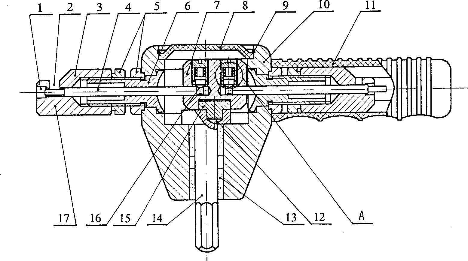
[0024] Such as Figure 1-13 As shown, the new sheet cutter is used in conjunction with a pistol electric drill, which can cut metal sheets below 2.2 mm or non-metal sheets below 5 mm, and can also cut arbitrary curves and round holes with a diameter greater than 25 mm. The cutting speed is fast, up to 1 m / min or more.

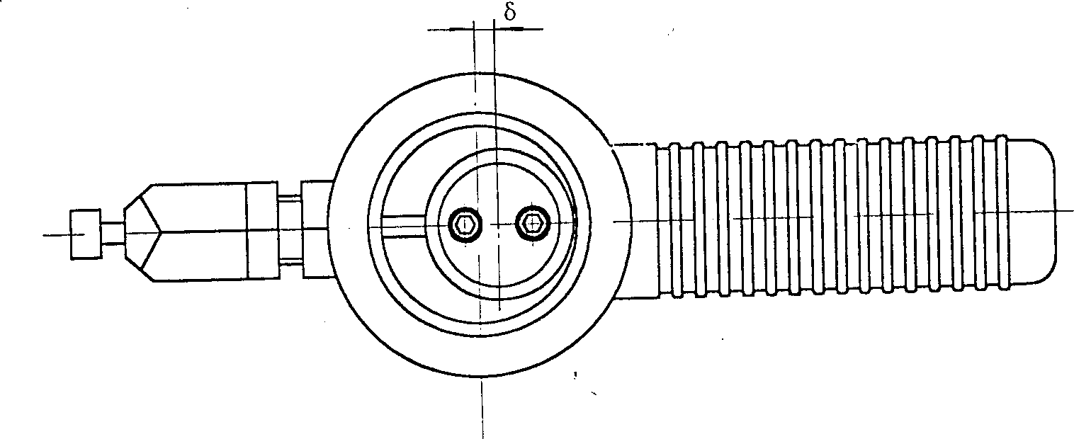
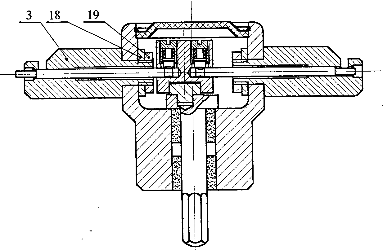
[0025] This cutter has a body 10 with a circular, conical or hexagonal shape, and the body has coaxial shaft holes that are perpendicular to each other and communicate with each other. figure 1 In the shaft hole in the vertical direction, there is an eccentric shaft 14 supported by an oil bearing 13 and driven by an external force with an eccentric distance δ of 2.5-3.5 mm. The eccentric shaft is embedded in the "T" shaft by a common "T" shaft The lower block 15 at the eccentric position of the end is formed, and a lubricating oil st...


PUM

PropertyMeasurementUnit
angleaaaaaaaaaa

Abstract

The sheet cutter is used in making sheet product, field decoration, repairing, etc. It consists of frame, eccentric shaft, upper sliding block, lower sliding block, guide sleeve, cutter seat, cutter rod and other parts and features the cutter rod separated into two parts set axially and oppositely and with fixed inner end and moving outer end inside the cutter seat, which is connected to the frame via the symmetrical guide structure. Driven by outer force, the eccentric shaft rotates at high speed to drive via the upper sliding block the upper sliding block and the cutter rod to reciprocate and thus to shear and cut sheet in either linear or curvilinear mode.

Description

technical field [0001] The invention relates to a thin plate cutting tool. Background technique [0002] In the metal sheet below 2.2 mm and non-metal sheet products below 5 mm industries, such as electrical boxes, stainless steel kitchen cabinets, safes, various containers, and sheet metal repair industries, automobile shell repair and decoration industries, often encounter For the cutting of some thin plates, of course, large batches can be cut by punches, shears and other equipment, but for some other cutting tasks, it can only be done by hand or electric scissors, gas cutting and other tools. The former is very laborious, and the latter can only be done. It is very troublesome to cut straight lines, and the board will be tilted up when cutting, and it is even more impossible to cut curves, inner holes or undulating boards such as corrugated boards. The cost of gas cutting is high, the efficiency is low, and the cut is not smooth. Therefore, the advent of a portable cut...

Claims


Application Information

Patent Timeline
Patent Type & Authority Applications(China)
IPC IPC(8): B23D27/02
Inventor 俞岳皋
Owner 俞岳皋
Why Eureka
Try Eureka