
Converter controlled power generator

An inverter-controlled technology, applied in the field of inverter-controlled generators, can solve problems such as difficulty in obtaining output power and reduced operating efficiency

Inactive Publication Date: 2002-08-14
HONDA MOTOR CO LTD
View PDF2 Cites 9 Cited by
  • Summary
  • Abstract
  • Description
  • Claims
  • Application Information

AI Technical Summary

Problems solved by technology

Especially in terms of output characteristics, when the generator is operated at a high speed in order to extract a large output power, it is difficult to obtain a sufficiently large output power, and the operating efficiency is reduced.

Method used


Image

  • Converter controlled power generator
  • Converter controlled power generator
  • Converter controlled power generator

Examples


Embodiment Construction

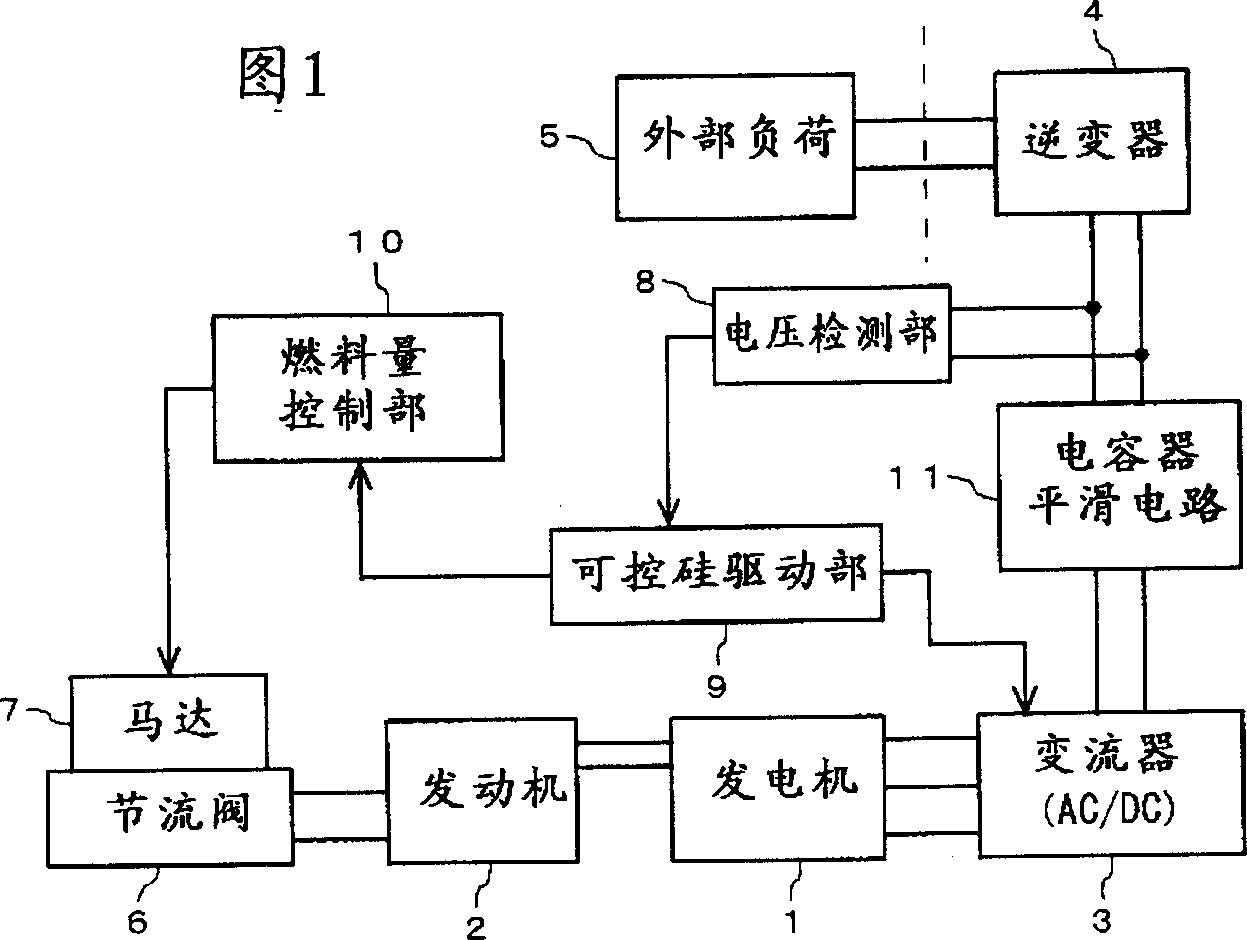
[0021] An embodiment of the present invention will be described in detail below with reference to the accompanying drawings. FIG. 1 is a functional block diagram showing an inverter-controlled engine. A permanent magnet multi-pole generator (hereinafter simply referred to as "generator") 1 is driven by an (internal combustion) engine 2 and generates multi-phase (typically 3-phase) alternating current. The generated alternating current is converted into direct current after full-wave rectification by the converter 3. The converter 3 is a rectification circuit formed by combining thyristors (generally semiconductor rectifying elements) as semiconductor rectifying elements into a bridge. constitute. The DC power is smoothed by the capacitor smoothing circuit 11 and input to the inverter 4, and the inverter 4 supplies single-phase AC power of a commercial frequency (for example, 50 Hz) to the external load 5 connected to the output side. In order to adjust the opening degree of ...


PUM


Abstract

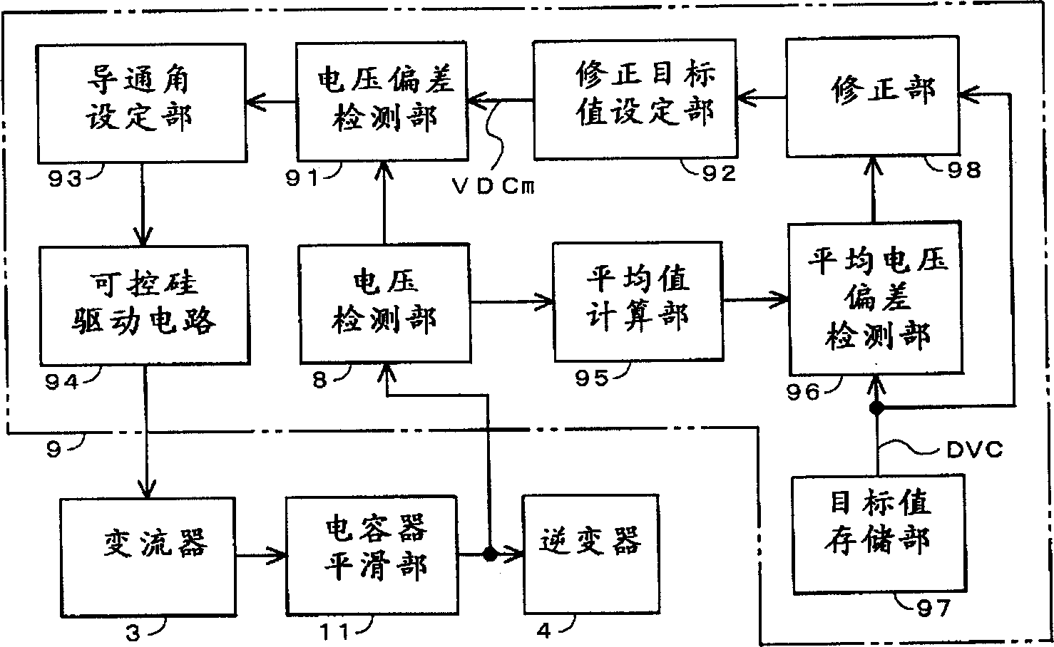
The performance of a generator is improved in a higher range of the output by correcting a decrease in the average direct current voltage supplied to an inverter. An average calculator 95 calculates an average of direct current voltage inputs to the inverter 4 for comparing with a target voltage (level) VDC. When it is judged by an average voltage deviation detector 96 that the average is smaller by a specific amount than the target voltage level, the target voltage level is increased by an adjusting unit 98. A conductor angle setting unit 93 determines the conduction angle of thyristors to change the voltage input of the inverter (4) to an adjusted target voltage level VDCm. A thyristor drive circuit 94 controls the conduction of the thyristors in the converter 3 according to the conduction angle.

Description

technical field [0001] The present invention relates to an inverter-controlled generator, and more particularly, to an inverter-controlled generator capable of operating the generator with good efficiency over a wide rotation range even if the output power of the inverter fluctuates. Background technique [0002] Inverters are increasingly used in motor generators used as AC power supply devices to stabilize output frequencies. Image 6 It is a block diagram showing an example of a power generation device using an inverter. The three-phase AC power generated by the generator 100 is converted into DC power by the rectifier 110 including a thyristor, and then input to the inverter 130 through the capacitor smoothing unit 120 . The inverter 130 converts the input DC power into AC power of a commercial frequency and outputs it. Such an inverter-controlled generator using a motor generator is described in JP-A-11-308896 and JP-A-6-121597. In an inverter-controlled generator, si...

Claims


Application Information

Patent Timeline
Patent Type & Authority Applications(China)
IPC IPC(8): F02D29/06H02M7/12H02P9/04H02P9/30
CPCH02P9/04H02P9/305
Inventor 清水元寿中村政史
Owner HONDA MOTOR CO LTD
Learn More