Control method and control device of brushless motor
A brushless motor, control method technology, applied in the direction of electronic commutation motor control, control system, electrical components, etc.
- Summary
- Abstract
- Description
- Claims
- Application Information
AI Technical Summary
Problems solved by technology
Method used
Image
Examples
Embodiment 2
[0137] Next, Embodiment 2 of the control device for a brushless motor of the present invention will be described. In the second embodiment, the same process as the above-mentioned first embodiment is performed to detect the crossing time from the detected induced voltage value, the direction of the induced voltage change, and the induced voltage reference value. However, the control device of Embodiment 2 is a device for correspondingly dealing with the case where the calculation of the switching time when it is judged that the intersection time cannot be detected or the time of the calculated switching time has exceeded the switching time Case.
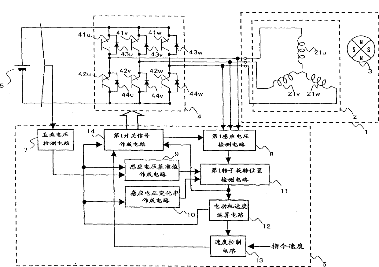
[0138] Hereinafter, a control method in the brushless motor control device according to the second embodiment will be described with reference to FIG. 11 . The configuration of Embodiment 2 is the same as that of Embodiment 1 described above.
[0139] When it is judged that the intersection time cannot be detected from the detectio...
Embodiment 3
[0143] Next, Embodiment 3 of the control device for a brushless motor according to the present invention will be described. In Embodiment 3, even when the cut-off time is short and the intersection time of the induced voltage reference value and the detected induced voltage can be detected during high-speed operation, the intersection time can be obtained by calculation. The control device of Embodiment 3 configured in this way can detect the rotor position with high precision and reduce the disorder of the current waveform even when the cut-off period is short and the delay of one control cycle produces a large angle difference during high-speed operation.
[0144] Hereinafter, a control method of the brushless motor control device according to the third embodiment will be described.
[0145] FIG. 12 is a block diagram showing the structure of a control device for a brushless motor according to Embodiment 3. FIG. In FIG. 12 , the same reference numerals as in Embodiment 1 ar...
Embodiment 4
[0163] Next, Embodiment 4 of the control device for a brushless motor according to the present invention will be described. In the fourth embodiment, when the induced voltage changes due to temperature change or the like, the table value correction of the induced voltage change rate creation circuit is performed. With such a structure, the control device according to the fourth embodiment can normally stably detect the rotational position of the rotor with high accuracy even when the temperature changes.
[0164] Hereinafter, a control method of the brushless motor control device according to the fourth embodiment will be described.
[0165] FIG. 17 is a block diagram showing the structure of a control device for a brushless motor according to Embodiment 4. FIG. In FIG. 17, the same reference numerals as those in FIG. 1 are assigned to the parts having the same configuration as those in the first embodiment, and description thereof will be omitted.
[0166] In the control de...
PUM
 Abstract
Description
Claims
Application Information
 - R&D
- Intellectual Property
- Life Sciences
- Materials
- Tech Scout
- Unparalleled Data Quality
- Higher Quality Content
- 60% Fewer Hallucinations
Browse by: Latest US Patents, China's latest patents, Technical Efficacy Thesaurus, Application Domain, Technology Topic, Popular Technical Reports.
© 2025 PatSnap. All rights reserved.Legal|Privacy policy|Modern Slavery Act Transparency Statement|Sitemap|About US| Contact US: help@patsnap.com


