Scraps exhausting belt conveyer system

A technology for conveyor belts and chips, applied in conveyors, separation methods, filtration and separation, etc., can solve problems such as large installation space, reduced efficiency, and increased energy consumption

Inactive Publication Date: 2002-12-11
美芙兰国际公司
View PDF0 Cites 12 Cited by
  • Summary
  • Abstract
  • Description
  • Claims
  • Application Information

AI Technical Summary

Problems solved by technology

This setup requires a large installation space as well as two separate power sources, which will increase energy consumption an

Method used


Image

  • Scraps exhausting belt conveyer system
  • Scraps exhausting belt conveyer system
  • Scraps exhausting belt conveyer system

Examples


Embodiment Construction

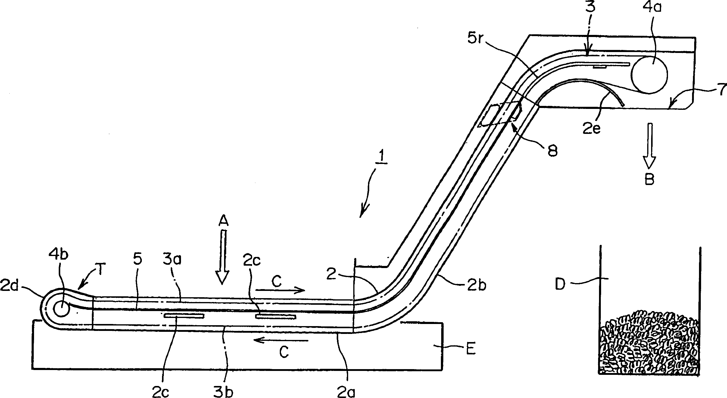
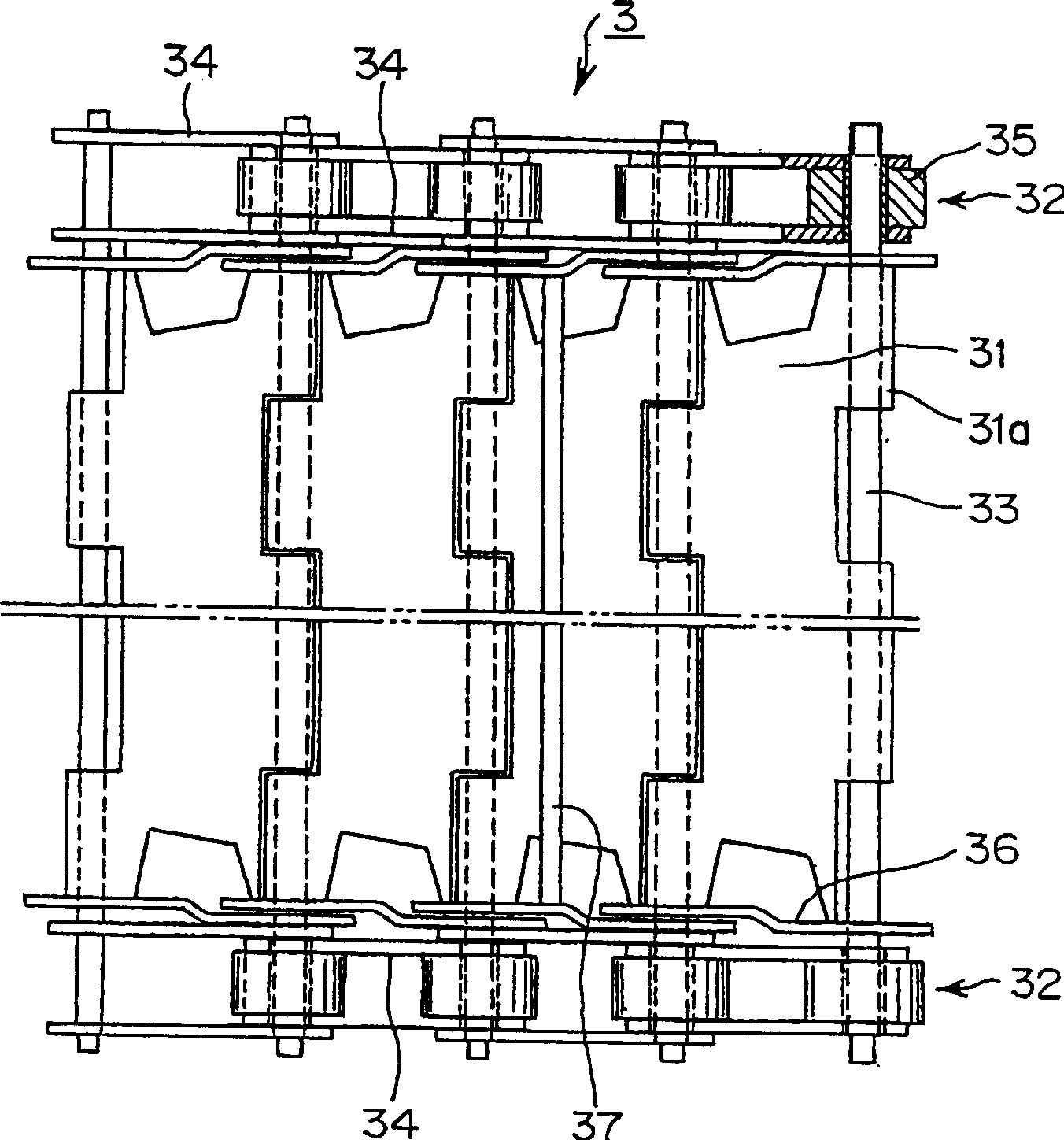
[0036] The following will combine Figures 1 to 7 A first preferred embodiment of the present invention will be described. Such as figure 1 with 2 As shown, the chip removal conveyor system 1 in this embodiment generally includes an endless hinged conveyor belt 3 circulating in the used coolant treatment tank 2, and a drive sprocket 4a surrounded by side chains 32 on both sides of the hinged conveyor belt 3, located at An end disc 4b at the belt end T for guiding and supporting the side chain 32, and a partition 5 between the discharge section 3a and the return section 3b of the articulated conveyor belt 3 and below the discharge section 3a. In the conveyor belt system 1 of this structure, the used coolant containing chips of different sizes is discharged into the used coolant treatment tank 2 from above (such as figure 1 shown by the middle arrow A), these chips are discharged from the right side of the used coolant treatment tank 2 (such as figure 1 indicated by the m...


PUM


Abstract

A chip removal conveyor system, comprising a partition (5) arranged below a discharge section (3a) of an endless hinged conveyor belt and facing the discharge section in length. An outer scraper (37) is connected to the outer peripheral surface of the hinged conveyor belt, and an inner scraper (38) is connected to the inner peripheral surface of the hinged conveyor belt. At the belt end (T) where the hinged belt turns upwards, the small chips (K2) collected by the return section (3b) of the hinged belt are held between the cylinder (6) and the hinged belt and conveyed to the partition (5) . The small chips are then conveyed along the partition (5) and eventually discharged out of the spent coolant disposal tank.

Description

technical field [0001] The present invention relates to a chip removal conveyor system in which used coolant containing chips of various sizes, including from machine tools during metalworking operations such as cutting or grinding, is discharged from above into a spent coolant disposal tank Cutting chips or grinding chips of iron-based, aluminum-based or copper-based metals produced, chips of different sizes contained in the used coolant are conveyed by a separate conveyor belt system, and then discharged outside the used coolant treatment tank . Background technique [0002] When machine tools perform metalworking operations, such as cutting or grinding, on metallic materials, coolants, such as water, containing cutting oils or lubricants are typically used to cool cutting tools, grinding tools and / or workpieces. Generally, when a chip removal conveyor system is used to collect and remove chips from the spent coolant discharged from the machine tool, a conveyor system con...

Claims


Application Information

Patent Timeline
IPC IPC(8): B23Q7/00B23Q7/03B23Q11/00B23Q11/08B65G19/14B65G19/18
CPCB23Q11/0057Y02P70/10B23Q11/1069B23Q7/00B23Q11/0825
Inventor 堀隆一松冈重德远藤坚一
Owner 美芙兰国际公司
Why Eureka
Try Eureka