Pneuamtic suction pipe connector for refuse recovering apparatus

A technology for recycling equipment and coupling devices, which can be used in suction hoses, cleaning equipment, mechanical equipment, etc., and can solve problems such as disconnection, damage to related parts, and low cost.

Inactive Publication Date: 2002-12-11
SEB SA
View PDF0 Cites 3 Cited by
  • Summary
  • Abstract
  • Description
  • Claims
  • Application Information

AI Technical Summary

Problems solved by technology

[0003] As we all know, the above-mentioned different parts of the pneumatic pipeline can be connected together only by nesting each other. Of course, the cost of implementation is very low, but there is a great defect: during the operatio

Method used


Image

  • Pneuamtic suction pipe connector for refuse recovering apparatus
  • Pneuamtic suction pipe connector for refuse recovering apparatus
  • Pneuamtic suction pipe connector for refuse recovering apparatus

Examples


Embodiment Construction

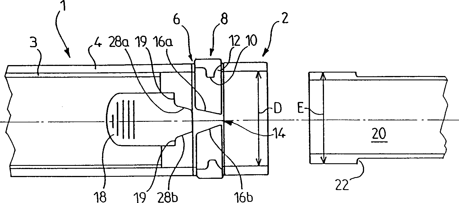
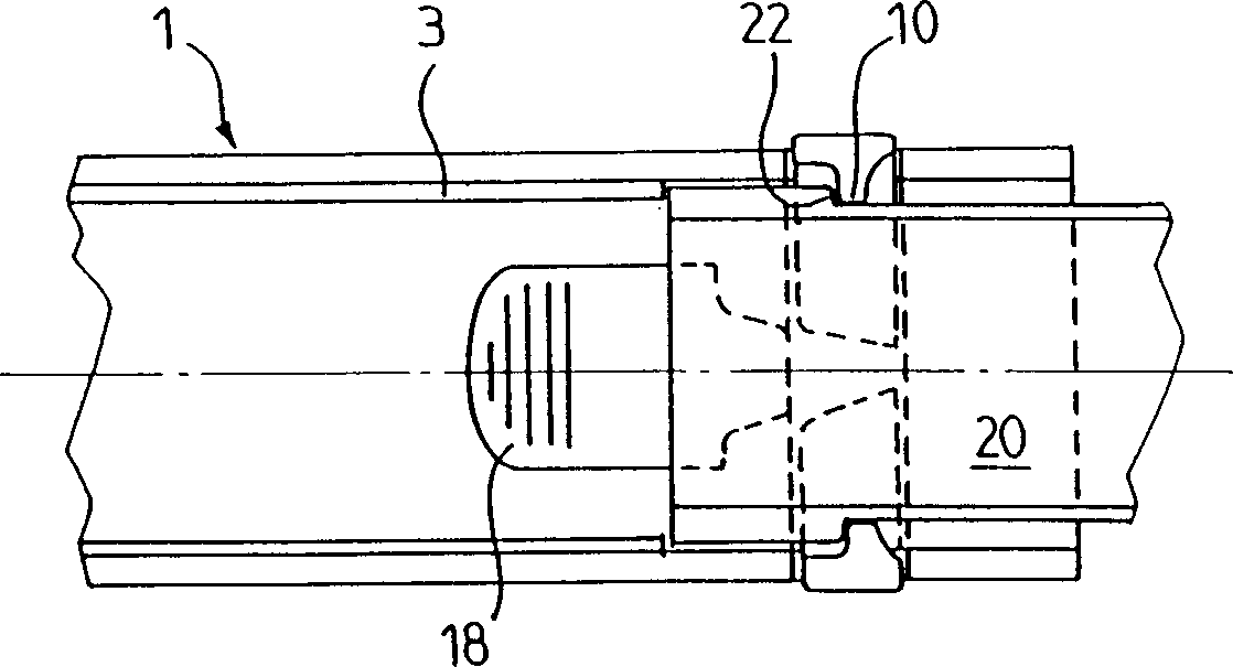
[0031] According to the present invention, if figure 1 In the embodiment shown, the tube 20 constitutes a part intended to be connected to another part 1 with an end 2 .

[0032] According to the embodiment shown, part 1 is a sleeve 4 mounted on pipe 3 , protruding from pipe 3 , the inner diameter D of which is slightly greater than the outer diameter E of pipe 20 . This feature enables the insertion of the tube 20 in the end 2 of the part 1 .

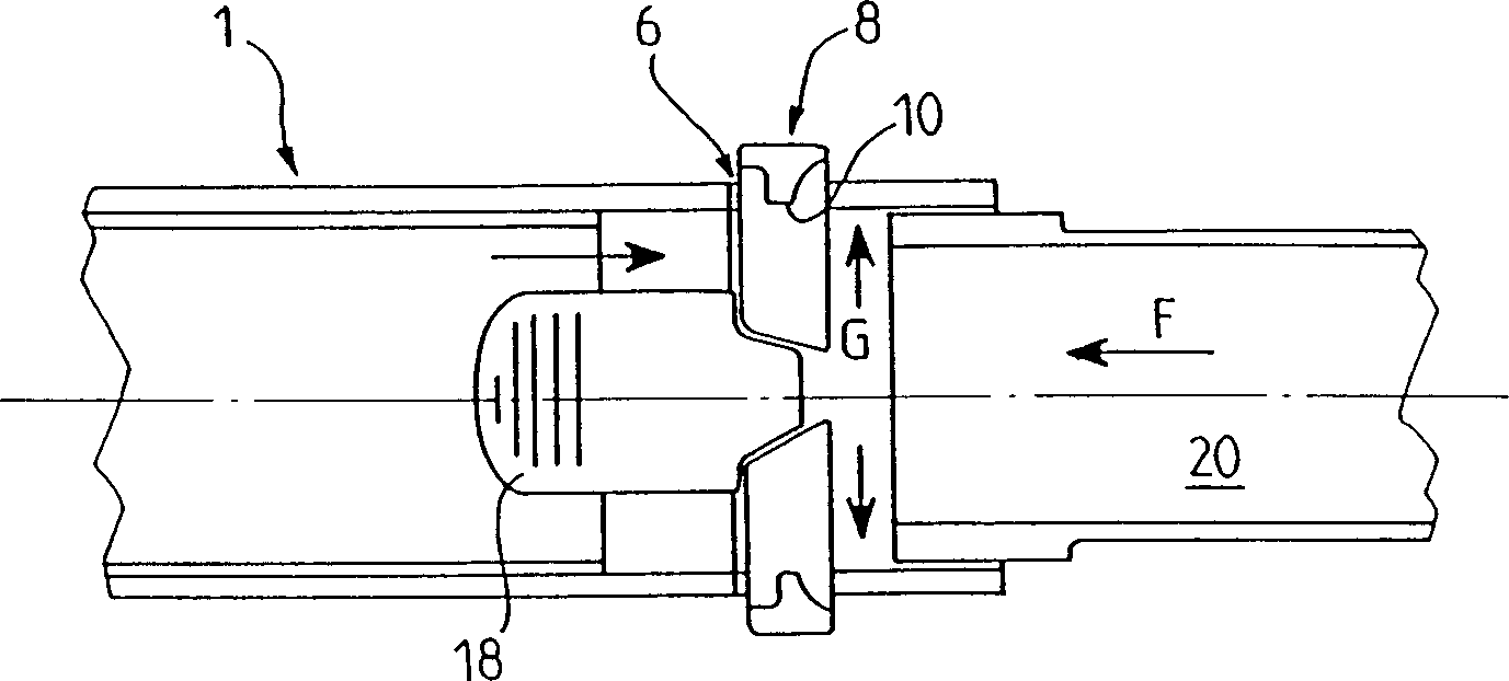
[0033] According to the invention, part 1 has a split elastic ring 8 which has the shape and function of a circlip. Thus, said elastic ring is split at 14 , which ring is arranged in the groove 6 of the end 2 of the part 1 . Advantageously, the ring has pins 10 towards the inside of the ring, as Figure 4 shown in .

[0034] According to the embodiment shown, the ring has a lug 11 which prevents rotation when the two parts on either side of the opening 14 are opened. This lug is not indispensable, especially if the symmetrical act...


PUM


Abstract

The connection is between two tubes (1) of a suction circuit of a waste recovery system each comprising a cylindrical end (2) which is inserted in the second end. The first end has a transverse shoulder (22) and the second end comprises a split elastic collar (8) housed in an end groove (6). The collar has a radial lug (10) passing through an end opening for engaging behind the first end shoulder when inserted in the second end. A collar spacing part (18) is housed in one of the ends.

Description

technical field [0001] The present invention relates to a dust recovery device of the vacuum cleaner type, in particular to a component coupling device constituting at least a part of a pneumatic suction pipe. Background technique [0002] Although the present coupling may be used between any two parts of the pneumatic suction tube of a vacuum cleaner, the invention is particularly directed to the user-operated pneumatic suction portion, which extends between the base of the vacuum cleaner and the suction head in the case of sliding vacuum cleaners. Thus, the pneumatic part may consist of several tubes or hoses, an operating handle, or even a detachable device for pre-filtering by gravity, inertia or cyclone. [0003] As we all know, the above-mentioned different parts of the pneumatic pipeline can be connected together only by nesting each other. Of course, the cost of implementation is very low, but there is a great defect: during the operation, the parts may often In add...

Claims


Application Information

Patent Timeline
IPC IPC(8): A47L9/24F16L37/088
CPCA47L9/242F16L37/0885
Inventor 阿兰·苏恩埃里克·盖勒兹
Owner SEB SA
Why Eureka
Try Eureka