Pumping source for multiband Raman amplifier

A pumping source and pumping technology, which is applied in the direction of instruments, lasers, phonon exciters, etc., can solve the problems of complex amplifiers, expensive amplifiers, and amplifiers that cannot be used effectively.

Inactive Publication Date: 2002-12-11
JDS UNIPHASE CORP
View PDF0 Cites 10 Cited by
  • Summary
  • Abstract
  • Description
  • Claims
  • Application Information

AI Technical Summary

Problems solved by technology

However, these amplifiers are more complex and expensive than C-band alone
And amplifiers tha

Method used


Image

  • Pumping source for multiband Raman amplifier
  • Pumping source for multiband Raman amplifier
  • Pumping source for multiband Raman amplifier

Examples


Embodiment Construction

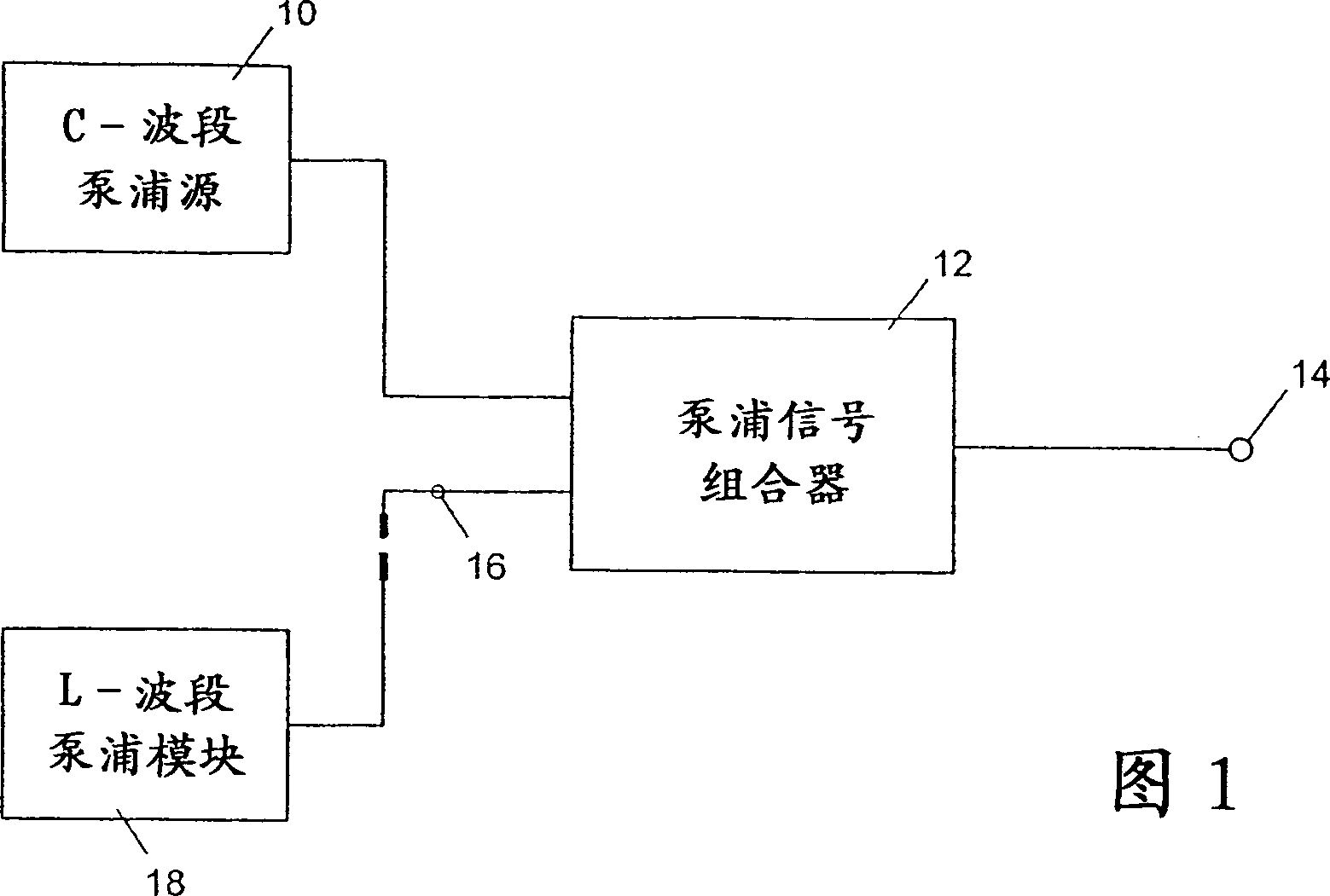
[0014] Fig. 1 is a general system structure schematic diagram according to the present invention, and the output end of C-band pumping source 10 is coupled into a pump signal combiner 12, can directly enter and be connected with the Raman gain medium that will pump from this Output 14. The C-band pump source 10 can be a combination of different light sources coupled together to provide a desired pump wavelength range with different energies. Such a wavelength combination can provide an ideal gain profile along the C-band. In particular, it is generally desirable to provide a pump source that yields a suitably smooth gain curve in the C-band, so that all multiplexed channels in the system achieve approximately uniform optical gain.

[0015] The pump signal combiner 12 in FIG. 1 also has a second input 16 for receiving the output from the L-band pump module 18 . The C-band pump and signal combiner 12 is set such that: when the L-band pump module 18 is not connected, it provide...


PUM


Abstract

The invention relates to a multi-band Raman amplifier pumping source, wherein an optical pumping device provides pumping sources for the Raman amplifier in a single C-band or C-band and L-band. The first pump unit provides the necessary optical pump energy for a flat gain response in the C-band. The second pump unit operates with an upgraded module capable of extending the pumping range to L-band. The second pump unit provides two pump energies for the extended part of the gain spectrum. The pump energy for the C-band will also compensate for any disruption of the gain spectrum. In this way, a flat gain response is maintained in the C-band and L-band. .

Description

technical field [0001] This invention relates to optical gain devices, and more particularly to pumping devices for optical gain devices utilizing stimulated Raman scattering. Background technique [0002] An optical gain medium is a device that, when supplied with optical pump energy, enhances the amplitude of a desired optical signal. Optical gain media can consist of optical fibers and are used in fiber lasers or fiber-based optical amplifiers. A technically known optical amplifier is based on the method of stimulated Raman scattering (SRS), commonly referred to as "Raman amplifier". In a Raman amplifier, optical pump energy is injected into the fiber medium used to transmit the amplified signal. Stimulated Raman scattering of the optical pump energy transfers the optical energy to a wavelength band longer than the pump wavelength due to excitation by the vibrational modes of the medium that provide longer-band gain. The Raman laser is similar to it, except that the Ra...

Claims


Application Information

Patent Timeline
IPC IPC(8): G02F1/35H01S3/094H01S3/10H01S3/30
CPCH01S3/094003H01S3/094096H01S3/302
Inventor 尼古拉斯·金
Owner JDS UNIPHASE CORP
Why Eureka
Try Eureka