
Improved intensified petroleum production method

A technology for oil production and carbon dioxide, which can be used in the fields of fluid production, earth-moving drilling, wellbore/well components, etc., and can solve problems such as unspecified results

Inactive Publication Date: 2002-12-18
THE BOC GRP INC
View PDF3 Cites 8 Cited by
  • Summary
  • Abstract
  • Description
  • Claims
  • Application Information

AI Technical Summary

Problems solved by technology

However, these given data do not indicate the use of 85% CO 2 and 100% CO 2 when the result

Method used


Image

  • Improved intensified petroleum production method
  • Improved intensified petroleum production method
  • Improved intensified petroleum production method

Examples


Embodiment

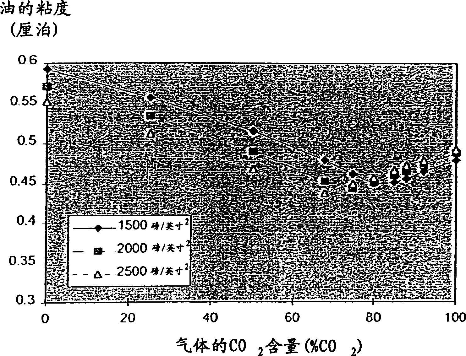
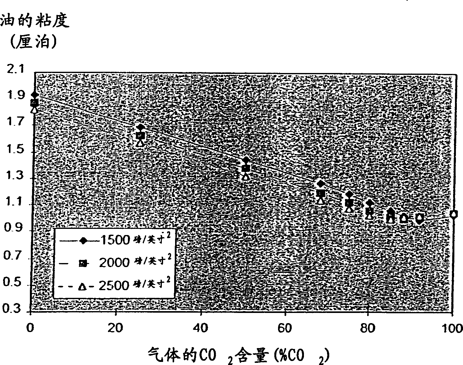
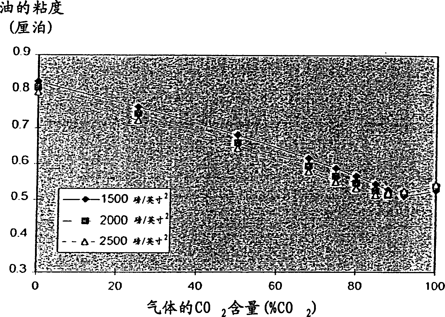
[0032]Three types of oil were studied to examine the effect of a mixture of carbon dioxide and nitrogen on enhancing oil recovery. A simulation method was developed based on the Peng-Robinson equation of state for gas-liquid equilibrium, the Twu model for liquid-phase viscosity, and the Brock and Bird equation for surface tension in a modified form. The three oils used in this study were paraffinic, naphthenic and aromatic. Assuming that the amount of mixed gas of carbon dioxide and nitrogen is 1 mole of gas / mole of oil, since the injection of carbon dioxide is usually after the water injection process, or alternately with water injection in the WAG method, a small amount of water should be added to this mixture. Water additions are based on 20% saturation of conventional oils. at 1,500-2,500 psi 2 The pressure and temperature of 75-200°F were studied.

[0033] figure 1 , 2 and 3 and Tables 1, 2 and 3 give the viscosity of paraffinic, naphthenic and aromatic oils at 75°F ...


PUM


Abstract

A method of increasing oil recovery from a subterranean formation is disclosed. Inject a mixed gas containing more than 50 volume percent carbon dioxide and the rest inert gas into the underground rock formation to reduce the viscosity and surface tension of the oil and increase the swelling of the oil. A mixed gas containing more than 60% by volume of carbon dioxide is preferable, and a mixed gas containing more than 70% by volume of carbon dioxide is more preferable.

Description

technical field [0001] The present invention provides methods of enhancing oil recovery from subterranean formations. More specifically, the present invention provides a method of injecting a gas mixture comprising at least 50% by volume carbon dioxide and the balance nitrogen or other inert gas into oil in a subterranean formation. Background technique [0002] The oil or gasoline and any water contained in the oil or the porous rock surrounding the oil or gasoline in the formation is generally under pressure due to the weight of the material lying on them. In doing so, they move to areas of lower and higher pressure, such as wellheads. After some pressure is released, the oil will still flow to the surface, but more slowly. This movement can be facilitated by a mechanical pump, such as the common grasshopper pump. These methods are commonly referred to as primary oil recovery methods. Usually, the primary oil recovery method can only recover less than 50% of the oil in...

Claims


Application Information

Patent Timeline
IPC IPC(8): E21B43/16
CPCE21B43/164
Inventor R·拉马钱德伦K·W·林贝奇黄顺成
Owner THE BOC GRP INC
Learn More