Great-moment oscillating piezoelectric ultrasonic motor

A technology of ultrasonic motor and high torque, applied in piezoelectric effect/electrostrictive or magnetostrictive motors, generators/motors, electrical components, etc., can solve problems such as limited applications

Inactive Publication Date: 2003-01-08
TSINGHUA UNIV
View PDF1 Cites 9 Cited by
  • Summary
  • Abstract
  • Description
  • Claims
  • Application Information

AI Technical Summary

Problems solved by technology

Its shortcoming is that its maximum torque output is only 550gfcm, and the lack of output torque limits its application in wider fields

Method used


Image

  • Great-moment oscillating piezoelectric ultrasonic motor
  • Great-moment oscillating piezoelectric ultrasonic motor
  • Great-moment oscillating piezoelectric ultrasonic motor

Examples


Embodiment Construction

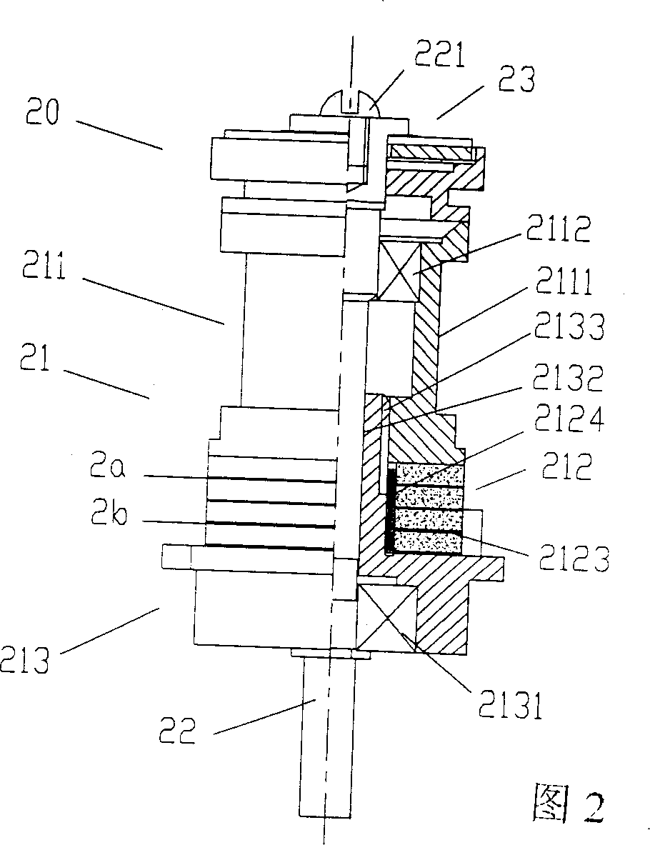
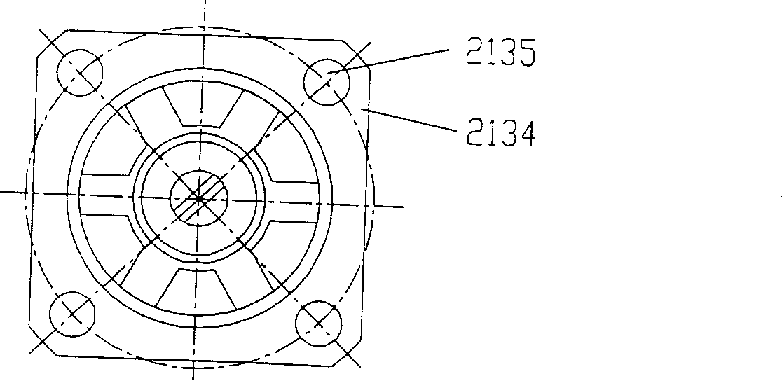
[0015] Please see Figure 2. The motor of the present invention is composed of a stator 21 , a rotor 20 , a central shaft 22 and a pressure mechanism 23 . Among them, the stator 21 is composed of an upper matching block 211 with a stepped structure shape 2111 of the ultrasonic horn type, and the two sides of the lower end are milled into a cake shape to facilitate the application of pre-tightening force, and a lower matching block with a square flange type base 2134 213 and four piezoceramic rings 212 tightly clamped in the middle by the inner thread of the upper matching block 211 and the screw structure 2133 of the lower matching block 213, the piezoelectric ceramic rings 212 are formed between the screw 2133 and the screw hole The clamping force of the ceramic sheet 212 is fixed (also can be bonded with epoxy resin glue). There is a screw 221 at the end of the central shaft 22 close to the rotor 20, so that the position of the central shaft 22 can be manually adjusted with ...


PUM


Abstract

The head shaking type piezoelectricity ultrasonic motor of large moment teatures in that the upper match blocks on the stator uses the bar type staircase structure of the ultrasonic amplitude of variation to simplify the structure, increase the moment. The joint parts between the rotor and the stator are pure plane in order to increase the carrying capacity. The adjusting screw is provided at the central shaft for alignment with the conected part. The maximum moment of the motor is 1.5kgfcm, increasing nearly 3 times. The stepping lifting is larger than 10 to the power 8 steps, raised 5 times. The motor can make continuous motion or stepping motion. The circular motion can be completed within 0-360 degree interval with any stepping angle. The external diameter can be adjusted within 2-40 mm.

Description

technical field [0001] The high-torque oscillating piezoelectric ultrasonic motor belongs to the technical field of piezoelectric ultrasonic motors. Background technique [0002] Piezoelectric ultrasonic motors are widely used as driving components of precision instruments due to their fast response speed and self-locking when power is off. The patent number is ZL97111805.1, and the name is "Piezoelectric Ultrasonic Micromotor Based on Bending Vibration Mode". Its structure is as follows figure 1 As shown: it includes a central shaft 12 and a stator 10 and a rotor 11 sleeved on the shaft. The stator 10 is composed of an upper matching block 101, a lower matching block 103 and a piezoelectric ceramic ring piece 102 tightly pressed therein. The inner wall of the stator 10 There is a pair of bearings 131 and 132, the central shaft is placed in the two bearings 131 and 132, and the pressure mechanism 14 is tightly fitted with the rotor 11, and the torque of the rotor 11 is outp...

Claims


Application Information

Patent Timeline
Patent Type & Authority Applications(China)
IPC IPC(8): H02N2/10H02N2/12
Inventor 褚祥诚李龙土桂治轮
Owner TSINGHUA UNIV
Why Eureka
Try Eureka