Eureka AIR delivers breakthrough ideas for toughest innovation challenges, trusted by R&D personnel around the world.

Control strategy of switch magnetic resistance driving system

A technology of switched reluctance drive and switching device, which is applied in the direction of motor generator control, AC motor control, electronic commutation motor control, etc., and can solve the problem of reducing the voltage rating of DC line capacitors, etc.

Inactive Publication Date: 2003-01-22
NIDEC SR DRIVES
View PDF5 Cites 0 Cited by
  • Summary
  • Abstract
  • Description
  • Claims
  • Application Information

AI Technical Summary

Problems solved by technology

[0008] No dead space is used in the prior art to derate the voltage rating of the DC line capacitors

Method used


Image

  • Control strategy of switch magnetic resistance driving system
  • Control strategy of switch magnetic resistance driving system
  • Control strategy of switch magnetic resistance driving system

Examples


Embodiment Construction

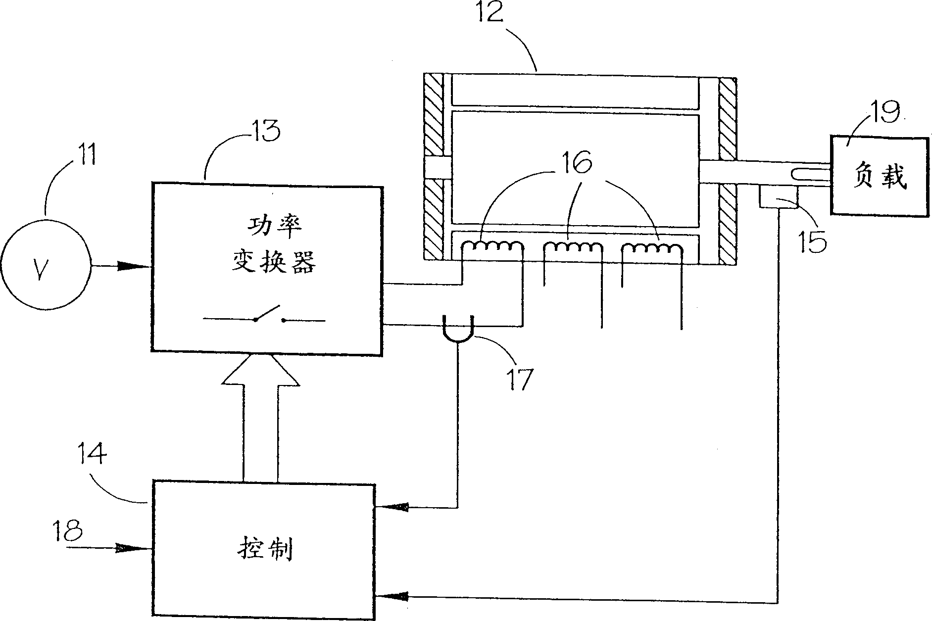
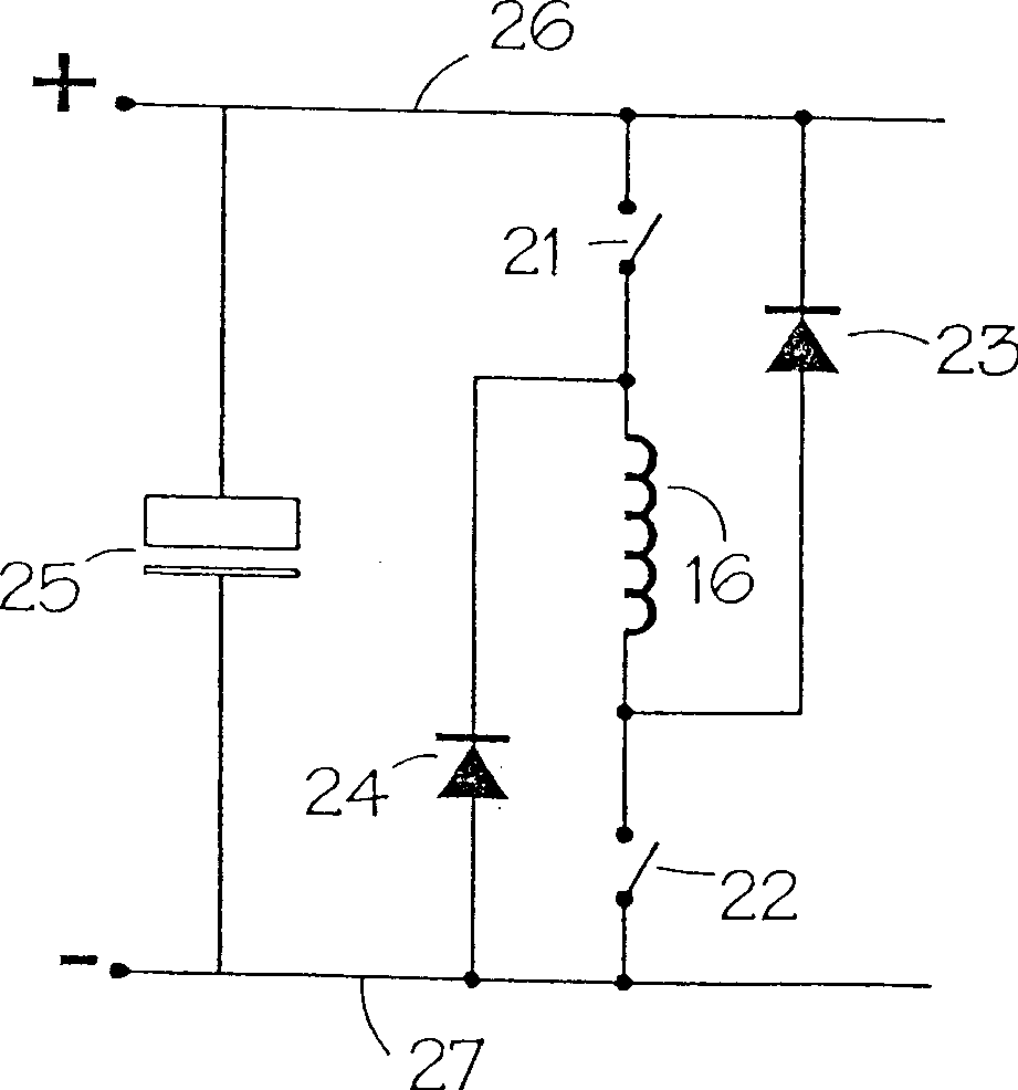
[0026] The invention can be implemented by a first embodiment in a drive system as shown in FIG. 1 with several switching circuits for each phase as shown in FIG. 2 . According to the invention, the control strategy is adapted to use a dead-running configuration of the switching circuit programmed by the controller 14 .

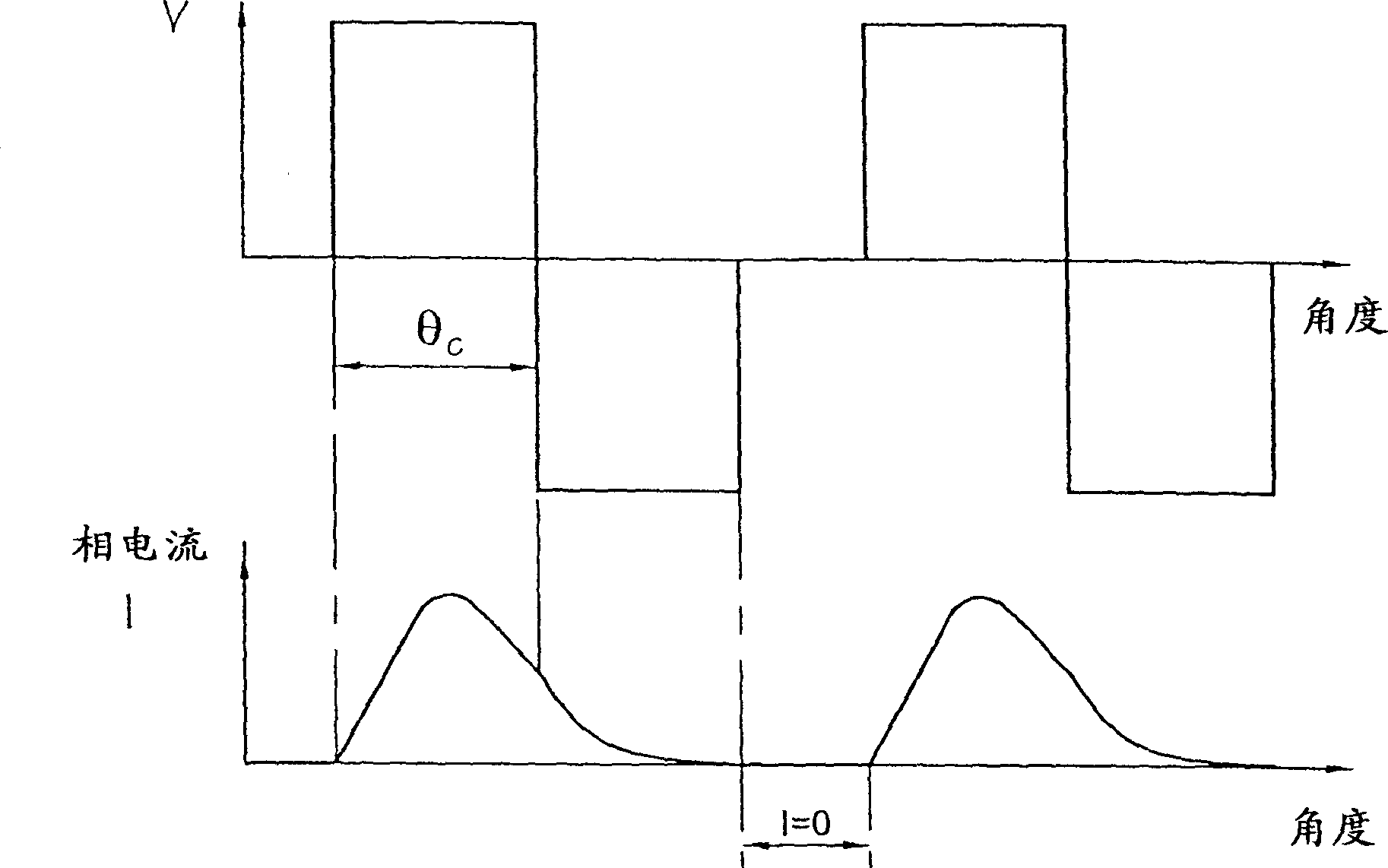
[0027]FIG. 5(a) shows the voltage waveform at the terminal of DC line capacitor 25 (ie, the DC line voltage) when one phase of the circuit of FIG. 2 is operated in a conventional manner to produce the phase current waveform of FIG. 3(a). The graph is drawn under ideal conditions where the voltage source 11 and the DC link capacitor have a minimum inductance. It can be seen that the DC link voltage is virtually constant, with short term very small spikes at the point where the phase is disconnected.

[0028] But in a real circuit, the source has resistance and inductance, and the capacitor and its connecting wires will also have some additional inductance. T...


PUM


Abstract

A switched reluctance drive is supplied from a power source and has a DC link, across which is a DC link capacitor. The phases of the machine are controlled by a controller which controls the switches connecting each phase winding to the DC link. The controller switches off the switches of each phase in a sequence which minimises the peak voltage appearing on the DC link capacitor, thereby allowing a reduction in the voltage rating of the capacitor.

Description

technical field [0001] The present invention relates to a method of reducing transient voltages in a switched reluctance drive system. Background technique [0002] The characteristics and operation of switched reluctance systems are well known in the art and have been described, for example, in the paper "Characteristics, Design, and Applications of Switched Reluctance Motors and Drives" by Stephenson and Blake, PCIM'93, Nurnberg, 21- 24 June 1993, which paper is hereby incorporated by reference. FIG. 1 schematically shows a conventional switched reluctance drive in which a switched reluctance motor 12 drives a load 19 . The input DC power source 11 can be a battery or rectified and filtered AC power. The DC voltage provided by the power supply 11 is converted across the phase winding 16 of the motor 12 through a power converter 13 under the control of the electronic control unit 14 . For the drive to work, this transition must be exactly synchronized with the angle of r...

Claims


Application Information

Patent Timeline
Patent Type & Authority Applications(China)
IPC IPC(8): H02P8/12H02P25/08
CPCH02P25/082H02P25/0925H02P25/08
Inventor 米切尔·保尔·坦卡德
Owner NIDEC SR DRIVES
Why Eureka
Eureka Blog
Learn More