Luminous unit for discharge lamp

A light-emitting device and discharge lamp technology, which is applied in the manufacture of discharge lamps, discharge tubes/lamps, components of gas discharge lamps, etc., can solve the position deviation of electrodes, the change of electrode positions in tubes, and the connection between discharge gaps and sealing parts Complicated heat fusion welding steps and other issues

Inactive Publication Date: 2003-01-29
杨炳霖
View PDF1 Cites 2 Cited by
  • Summary
  • Abstract
  • Description
  • Claims
  • Application Information

AI Technical Summary

Problems solved by technology

[0005] In this type of light-emitting device, there is a problem that it is very difficult to align the electrodes in the light-emitting tube at a predetermined position, and when the two ends of the light-emitting quartz tube are heated and extruded, the electrodes in the tube The location of the
Furthermore, a complicated heat fusion welding step is required to connect the discharge gap portion and the sealing portion, so there are many problems in terms of mass production and prolonging the service life.
[0006] In particular, when the discharge lamp is used on a vehicle, a movie camera or a slide projector, the position of the electrode facing inside it deviates due to the deviation of the luminous tube from the predetermined position, resulting in the problem that the desired focusing effect cannot be obtained.

Method used


Image

  • Luminous unit for discharge lamp
  • Luminous unit for discharge lamp
  • Luminous unit for discharge lamp

Examples


Embodiment Construction

[0023] Preferred embodiments of the present invention will now be described with reference to the accompanying drawings.

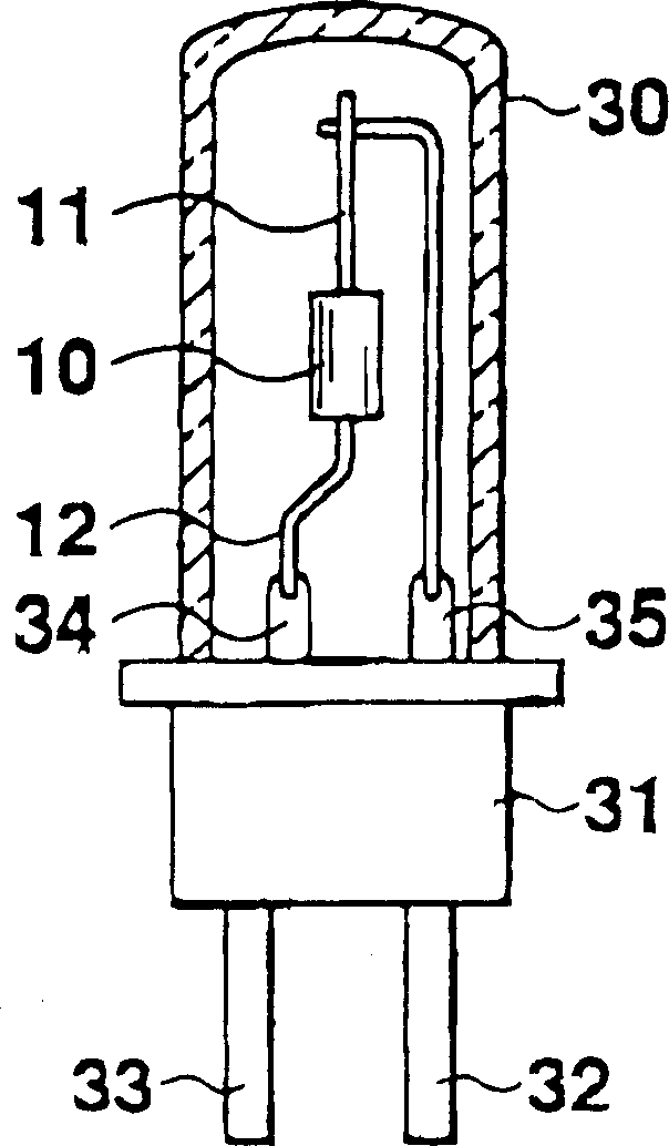
[0024] figure 1 is a metal halide lamp with a lighting device 10 designed according to the invention. The halogen lamp has an open end of a glass outer tube sealed with a power socket 31 . Two prongs 32 and 33 of the socket are fixed on the power socket 31 to be connected with the power supply. A light emitting device 10 is housed in the outer glass tube 30 . The axial electrodes 11 and 12 installed at both ends of the light emitting device 10 are electrically connected to socket pins 32 and 33 through wires 34 and 35 . The inside of the outer glass tube 30 is filled with inert gas.

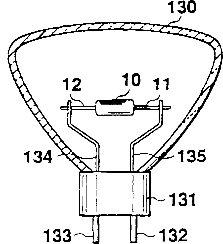
[0025] figure 2 Shown is a motor vehicle light with a lighting device 10 designed according to the invention. The structure of outer glass tube 130 and socket 131 and figure 1 same as described, therefore, figure 2 and figure 1 The numbering of the corresponding co...


PUM


Abstract

The ivnented illuminator of the discharge lamp includes the tube shaped case shell mode of transparent material, a pair of discharge electrodes with the gap between them, inserted into the case shelland the closure plug. The electrode axes of the discharge electrodes are fixed on the closure plug respectively. The position of the discharge electrode can be adjusted along the axis direction in the case shell. The discharge gas is filled in the discharge chamber formed by the case shell and the closure plug. The lamp can be widely used in the daily life and industrial area, such as street lamps, hanging type projection lamps and in cine-cameras, slide projectors as the lighting instrument for advertisement and illumination.

Description

technical field [0001] The invention relates to a light-emitting device for a discharge lamp, in particular to a light-emitting device for a discharge lamp with a simple structure, suitable for mass production, and an ultra-long service life. Background technique [0002] Discharge lamps with high-efficiency light emitting devices are widely used in daily and industrial fields, such as: street lamps, wall-mounted projection lamps and lamps for advertising or lighting in vehicles, movie cameras or slide projectors, etc. In these various discharge lamps, a pair of discharge electrodes facing each other are placed in a discharge cavity filled with luminescent gas, and the luminous effect is obtained by applying a predetermined voltage between the two electrodes to excite the luminescent gas. A variety of luminous brightness and luminous colors can be obtained by selecting different luminous gases, pressure of the discharge chamber or other characteristics. [0003] The common ...

Claims


Application Information

Patent Timeline
Patent Type & Authority Applications(China)
IPC IPC(8): H01J61/073H01J9/32H01J17/18H01J61/00H01J61/06H01J61/30H01J61/36H01J61/54H01J61/86
CPCH01J61/30H01J61/36
Inventor 杨炳霖
Owner 杨炳霖
Why Eureka
Try Eureka