Rolling bearing and bearing unit

A bearing device and bearing technology, which is applied in the direction of shafts and bearings, rolling contact bearings, bearing assembly, etc., can solve problems such as enhancement, insufficient restraint of bearing dynamic friction torque, large vibration, etc.

Inactive Publication Date: 2003-02-26
NSK LTD
View PDF2 Cites 16 Cited by
  • Summary
  • Abstract
  • Description
  • Claims
  • Application Information

AI Technical Summary

Problems solved by technology

[0016] However, in the above-mentioned prior art bearing device, problems to be solved are still found: that is, when the bearing rotates, its rotational torque and fluctuations in the rotational torque are large, and vibration asynchronous with the rotation of the bearing device (also called for NRRO) is also larger
[0033] However, in this type of bearing device, the following problems are still found: that is, when the bearings rotate, since the lubricant is sealed in the grooves of the two bearings, the rotational torque of the device and the variation of the rotational torque are large, and the device The non-synchronous vibration (NRRO) of the rotation is also larger
[0041] However, recently, with the increase of the rotational speed of various rotating devices, the demand for reducing the dynamic friction torque of bearings has been strengthened, that is, simply reducing the contact angle by the above-mentioned method cannot sufficiently restrain the bearing dynamics caused by the high-speed rotation of the bearing. friction torque
[0042] Specifically, the high-speed rotation of the bearing causes the grease present inside the bearing to move more, and especially the grease that has moved to the inner diameter side of the outer ring due to centrifugal force is stirred between the inner diameter side of the outer ring and the outer diameter portion of the cage, Thus, the churning resistance or shearing resistance is increased, resulting in an increase in the dynamic friction torque of the bearing

Method used


Image

  • Rolling bearing and bearing unit
  • Rolling bearing and bearing unit
  • Rolling bearing and bearing unit

Examples


no. 1 example

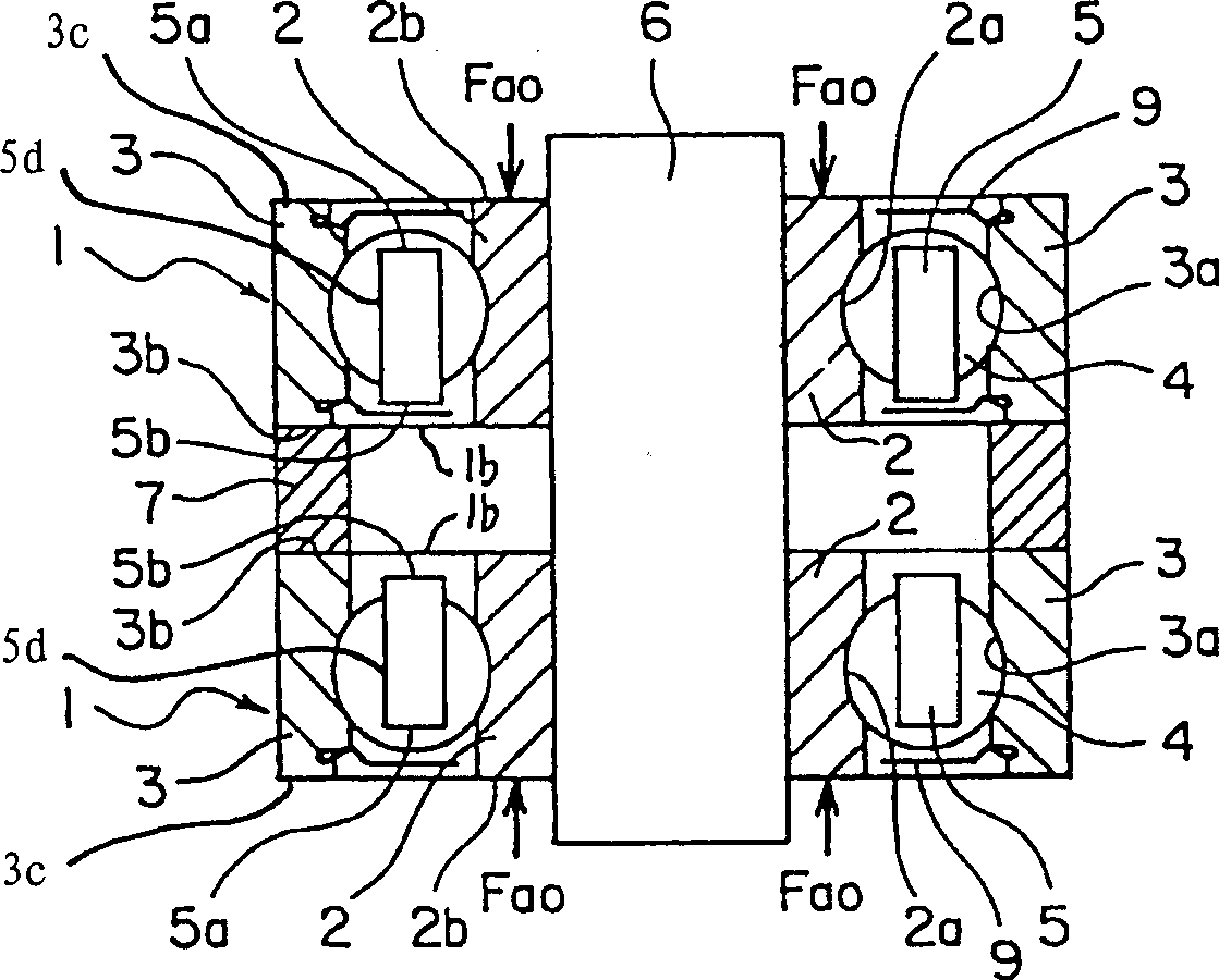
[0125] here, figure 1 A first embodiment of a bearing arrangement according to the invention is shown. This bearing device includes two rolling bearings 1 and 1, wherein the two rolling bearings 1 and 1 are respectively fixed to the outer circumference of the shaft 6 with the inner rings 2 and 2 of the two rolling bearings and the preload (axial load) is applied to the two rolling bearings combined in the above manner. Also, in this embodiment, a description of the structure will be given using two bearings as a pair, however, the present invention is not limited to such a combination of two bearings.

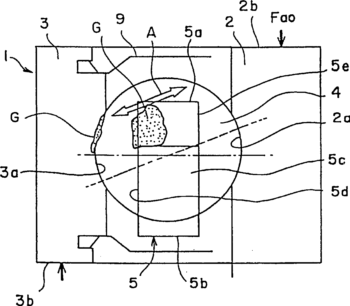
[0126] The rolling bearing 1 is a ball bearing, which includes an inner ring having an inner raceway 2a formed on its outer periphery, an outer ring having an outer raceway 3a formed on its outer periphery, a plurality of rolling rollers inserted between the inner raceway 2a and the outer raceway 3a elements 4, and crowned cages 5 for holding the rolling elements 4 at regula...

no. 2 example

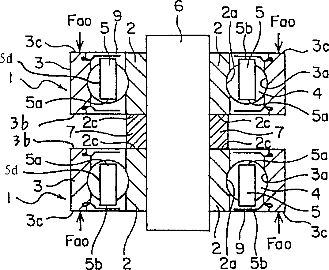
[0134] Now, image 3 A second embodiment of a bearing arrangement according to the invention is shown.

[0135] This embodiment differs from the first embodiment in that the sheath opening sides 5a and 5a of the cages 5 and 5 of the two rolling bearings 1 and 1 are arranged opposite to each other and in that the preload is applied not only to the On the end faces 2c and 2c of the inner rings 2 and 2 on the side 5a and 5a, and on the end faces 3c and 3c of the outer rings 3 and 3 on the opposite side 5b and 5b of the cage sheath opening, therefore, the inner ring 2. The outer ring 3 , the rolling elements 4 , and the cage 5 are not limited to any particular one, but any structure may be adopted, and therefore, by adopting the first embodiment, a detailed description thereof is omitted here.

[0136] According to this embodiment, between the inner rings 2 and 2 of the rolling bearings 1 and 1, a spacer 7 is inserted, and the preload Fao is applied to the outer rings 3 and 3 fro...

no. 3 example

[0140] Now, Figure 4 A fourth embodiment of a bearing arrangement according to the invention is shown.

[0141] The bearing device according to the present embodiment includes a housing 10 whose inner periphery is formed with double rows of raceways 10a and 10a; One raceway 10a is opposed; a separately formed inner ring 2 which can be fixed to another part of the outer circumference of the shaft 6 so that its raceway 2a is opposed to the other raceway 10a of the housing 10; and a plurality of rolling elements (Balls) 4... and 4..., which are installed between one raceway 10a of the housing 10 and the raceway 6a of the shaft 6 and the other raceway 10a of the housing 10 and Between the raceways 2a of the inner ring 2.

[0142] And in this example, if Figure 4 As shown, the left side of the shaft 6 is fixed, while the right side end face 2b of the separately formed inner ring 2 on the right side is pushed, thereby applying a preload Fao. Therefore, this type of preload pro...


PUM


Abstract

In a bearing apparatus which is composed of two bearings each including a crown-shaped retainer and in which a lubricant is filled into its raceways, a preload is applied from the retainer pocket-opening side end face of an inner ring, and also a preload is applied from the retainer counter-pocket-opening side end face of an outer ring.

Description

technical field [0001] The present invention relates to improvements in bearing arrangements for spindles (also known as SPMs), such as those found in hard disk drives (also known as HDDs) and video cassette recorders (also known as VCRs). [0002] The present invention relates to a rolling bearing and a bearing device for small motors mainly used in information equipment and household appliances. [0003] This invention relates to improvements in bearing arrangements for various rotating devices, such as spindle motors in hard disk drives (also known as HDDs) and video cassette recorders (also known as VCRs). [0004] The present invention relates not only to reducing the vibration and noise of the bearing arrangement used to support the motor shaft, such as the spindle and the The drum spindle found in a Video Cassette Recorder (also known as a VCR). [0005] The present invention relates to rolling bearings and bearing arrangements for small motors used in hard disk drive...

Claims


Application Information

Patent Timeline
Patent Type & Authority Applications(China)
IPC IPC(8): F16C19/16F16C19/56F16C23/08F16C33/41F16C33/66F16C35/12F16C43/04
CPCF16C23/08F16C43/04F16C19/06F16C19/56F16C33/6614F16C19/547F16C33/6651F16C35/12F16C33/416F16C2240/40F16C33/6607F16C41/008F16C25/083F16C2240/42
Inventor 石和田博青木护宫崎晴三绳本大纲荒牧宏敏
Owner NSK LTD
Why Eureka
Try Eureka