
Wafer cleaner

A wafer cleaning and wafer technology, which is applied to cleaning methods and utensils, cleaning methods using liquids, electrical components, etc., and can solve the problems of waste of chemical cleaning agents, poor device effect, and inability to temporarily store chemical cleaning agents on the surface of wafers, etc. , to avoid rapid dispersion and maintain the effect of cleanliness

Inactive Publication Date: 2003-02-26
MACRONIX INT CO LTD
View PDF0 Cites 14 Cited by
  • Summary
  • Abstract
  • Description
  • Claims
  • Application Information

AI Technical Summary

Problems solved by technology

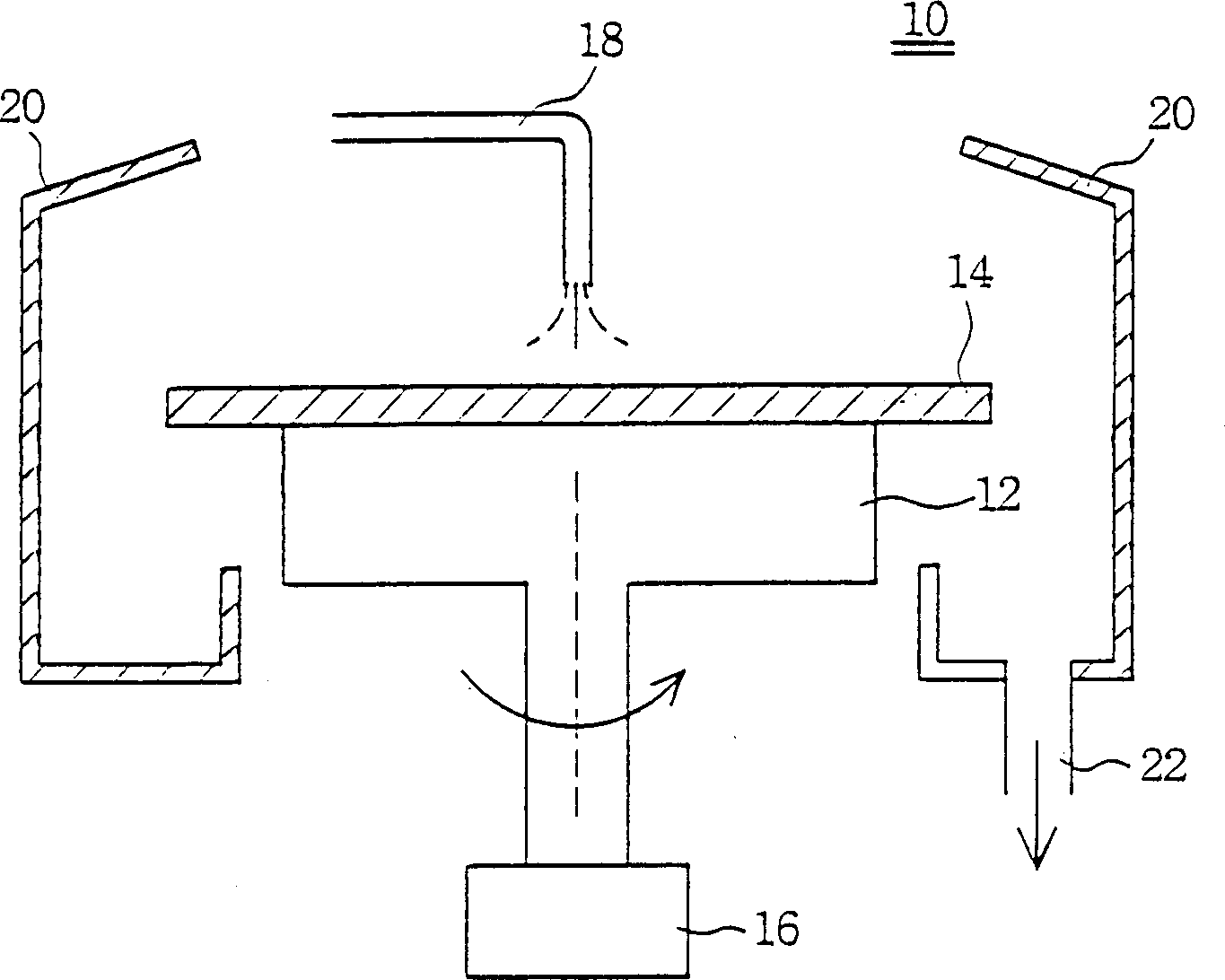
However, the traditional cleaning method only relies on pure centrifugal force, so this device cannot effectively remove a large number of particles attached to the wafer, especially some particles are firmly adhered to the surface of the wafer, so the effect of the device is not good
And the traditional method of using centrifugal force, the chemical cleaning agent will be quickly thrown off the surface of the wafer due to the centrifugal force, and the chemical cleaning agent cannot be temporarily stored on the wafer surface, so the chemical cleaning agent is often wasted

Method used


Image

  • Wafer cleaner
  • Wafer cleaner
  • Wafer cleaner

Examples


Embodiment Construction

[0025] Without limiting the spirit and scope of application of the present invention, the implementation of the present invention is described below with an embodiment; those skilled in the art, after understanding the spirit of the present invention, can apply this method to various On the chemical cleaning device, to eliminate the disadvantages of poor cleaning effect and waste of too much chemical cleaning agent when traditionally relying on centrifugal force alone for chemical cleaning, the application of the present invention should not be limited to the embodiments described below .

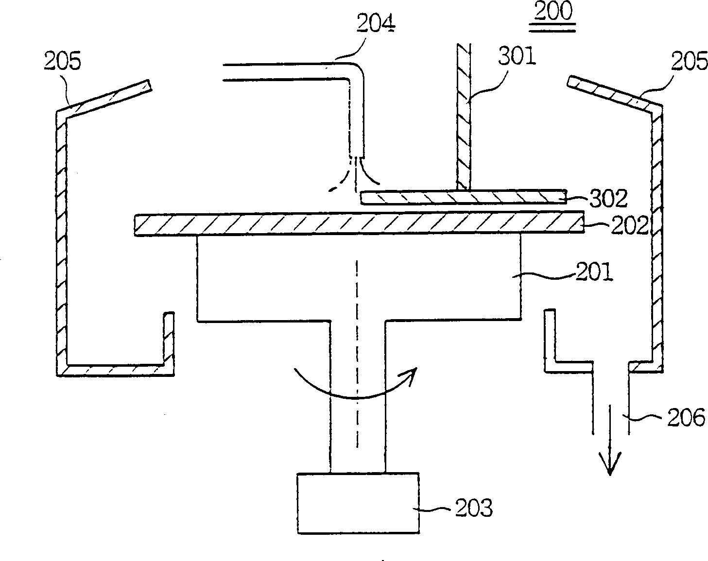
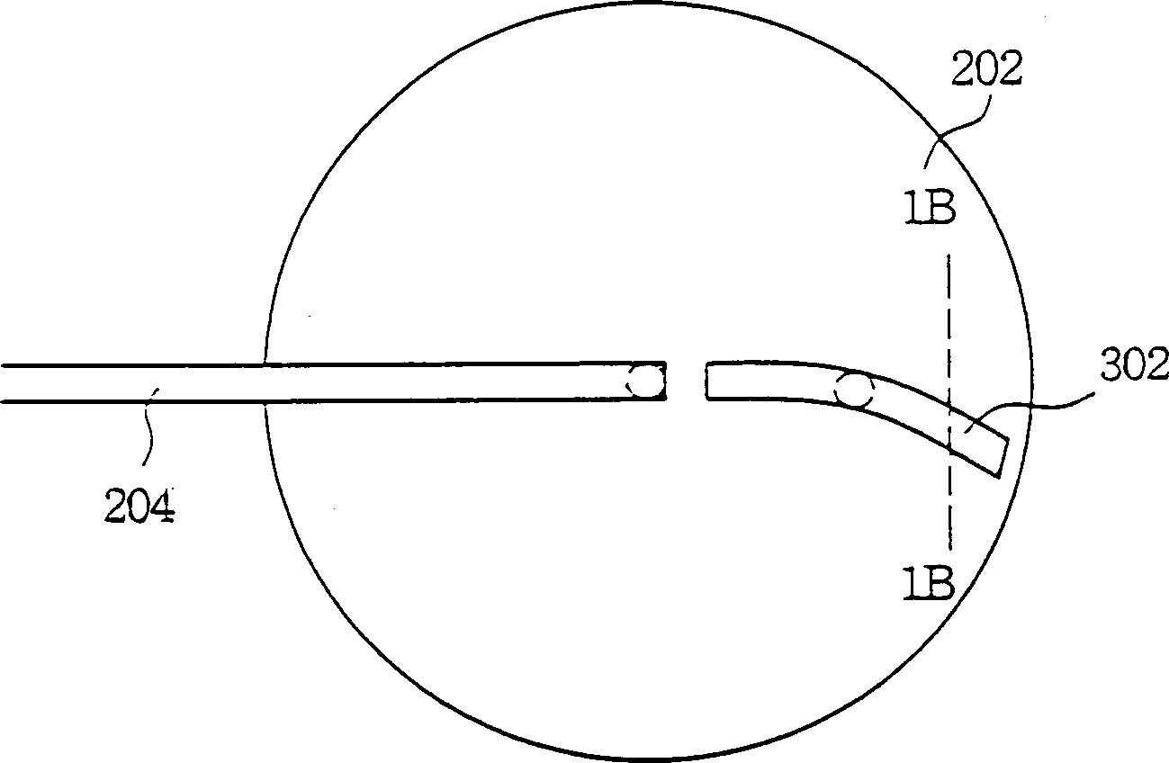
[0026] The wafer cleaning device of the present invention mainly includes two parts. The first part uses the centrifugal force of rotation to remove particles attached to the wafer with chemical cleaning agents. The second part is a curved brushing device. The curved brushing device is used to generate a shear stress to remove the wafer. At the same time, the curved device can block the che...


PUM


Abstract

The wafer cleaner includes at least a rotary stage to support wafer, a rotating unit to rotate the stage, a movable or fixed bent brush to clean the surface of wafer, a chemical cleaning head to spray chemical solvent to the surface of the wafer and a barrier wall to collect and block used detergent. The said cleaner has high wafer clenaing effect in relatively lower detergent consumption.

Description

technical field [0001] The invention relates to a wafer cleaning device, in particular to a wafer cleaning device capable of improving the wafer cleaning performance without increasing the amount of cleaning agent used. Background technique [0002] In recent years, high-density semiconductor components are in a vigorous development stage, and many semiconductor components belong to the submicron technology range. Therefore, there are often some unique developments in the process to meet the needs of sub-micron. Many different materials are used in the semiconductor manufacturing process. After forming a specific film layer, the required structure is usually produced by etching lithography, etching or planarization processes. Before the semiconductor process is applied, it usually enters the chemical station for cleaning to clean and remove the impurities on the surface. [0003] figure 1 A conventional wafer particle cleaning or removal apparatus 10 is shown. It compris...

Claims


Application Information

Patent Timeline
Patent Type & Authority Applications(China)
IPC IPC(8): B08B3/02H01L21/304H01L21/306
Inventor 梁明中蔡信谊
Owner MACRONIX INT CO LTD
Learn More