Hollow form member of cast-in-place concrete

A formwork component and hollow mold technology, which is applied to building components, building structures, floor slabs, etc., can solve the problems of complex production process, difficulty in integral molding of formwork components, and high cost.

Inactive Publication Date: 2003-03-12
湖南邱则有专利战略策划有限公司
View PDF1 Cites 51 Cited by
  • Summary
  • Abstract
  • Description
  • Claims
  • Application Information

AI Technical Summary

Problems solved by technology

However, this formwork member is a closed-cavity polyhedron structure, and the specific structural relationship between the upper bottom, the lower bottom, and the surroundin

Method used


Image

  • Hollow form member of cast-in-place concrete
  • Hollow form member of cast-in-place concrete
  • Hollow form member of cast-in-place concrete

Examples


Embodiment Construction

[0060] The present invention will be further described below in conjunction with the accompanying drawings and embodiments.

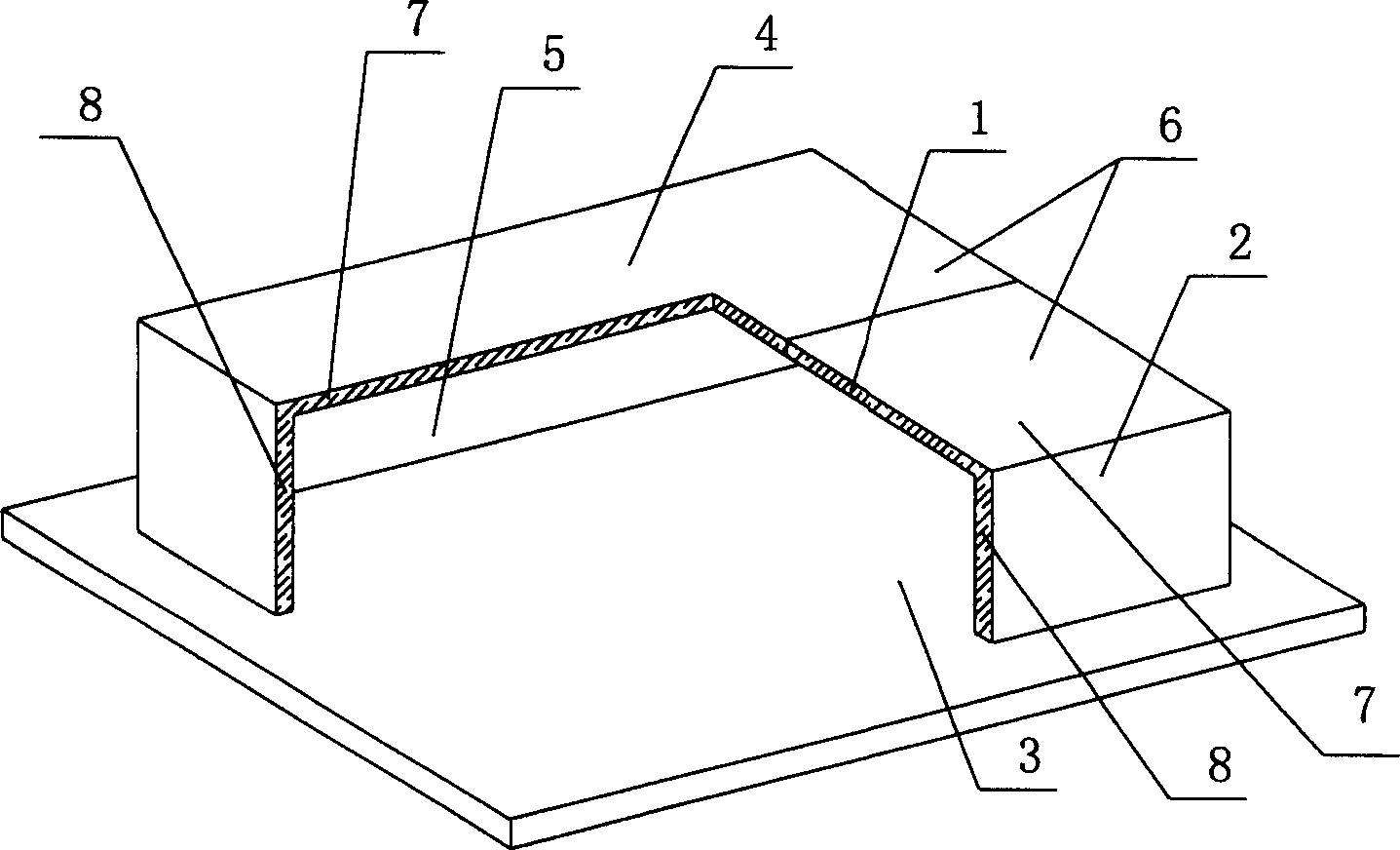
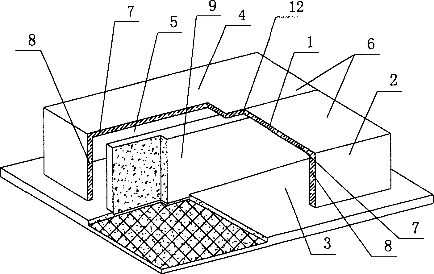
[0061] As shown in the accompanying drawings, the present invention includes an upper plate 1, surrounding side walls 2, and a lower bottom 3. The upper plate 1 and the surrounding side walls 2 form a mold shell 4, and the mold shell 4 and the lower bottom 3 form a closed cavity 5. It is characterized in that the formwork 4 is spliced ​​and assembled by at least two segmented formwork panels 6 , and the segmented formwork panels 6 are molded parts including a part of the upper plate 7 and a part of the side wall 8 connected thereto. figure 1 It is a structural schematic diagram of Embodiment 1 of the present invention. In each drawing, 1 is the upper plate, 2 is the surrounding side wall, 3 is the lower bottom, 4 is the formwork, 5 is the cavity, 6 is the block formwork plate, 7 is part of the upper plate, 8 is part of the side Walls with the same numb...


PUM


Abstract

A hollow form for in-situ pouring concrete is composed of the form unit and bottom plate, and is characterized by that form unit consists of top plate and peripheral wall and is divided into two halves. Its advantages are simple structure, high strength, low cost and easy manufacture.

Description

(1) Technical field [0001] The invention relates to a cast-in-place concrete hollow formwork component. (2) Background technology [0002] At present, most buildings with brick-concrete structure and frame structure use prefabricated hollow-core slabs as floor slabs, which have the advantages of fast construction speed and low cost. However, because there is no firm connection between two adjacent prefabricated hollow slabs, only cement mortar is used to fill the joints, so the integrity is poor, which is not conducive to earthquake resistance, and cracks and water seepage often occur in the gaps. In order to solve the above problems, many buildings adopt the method of cast-in-place concrete floor slabs (solid and hollow). Although the problems of earthquake resistance and cracking have been solved, a large number of templates are used during construction, which not only increases the cost, but also slows down the construction speed and prolongs the construction period. dea...

Claims


Application Information

Patent Timeline
IPC IPC(8): E04B5/36
Inventor 邱则有
Owner 湖南邱则有专利战略策划有限公司
Why Eureka
Try Eureka