Method for determining optimal position of lens in scanning head

A technology for determining the best position and method, applied in image data processing, optics, instruments, etc., can solve problems such as the inability to adjust the lens to the best state, the inability to accurately control the lens feed, and the need for high proficiency in operations, and achieve education Training and proficiency requirements are not high, the effect of highlighting creative features and reducing labor intensity

Inactive Publication Date: 2003-03-12
力捷电脑(中国)有限公司
View PDF0 Cites 1 Cited by
  • Summary
  • Abstract
  • Description
  • Claims
  • Application Information

AI Technical Summary

Problems solved by technology

Obviously, the above-mentioned adjustment method has great defects for such high-precision optical image components as the lens: 1. There are errors in the numerical judgment, and the poor stability of the person leads to the deviation of the lens position. As a result, it is impossible to adjust each lens. to the best state; 2. When using the adjustment stick to adjust the feed amount of the lens forward and backward cannot be accurately controlled, and there are often over-adjustment or under-adjustment phenomena, it is difficult to achieve an optimal and relatively average MTF value in each area 3. The speed is slow, the adjustment efficiency is not high, and the requirements for the proficiency of the operation are high, and the operator's education and training takes a long time

Method used


Image

  • Method for determining optimal position of lens in scanning head
  • Method for determining optimal position of lens in scanning head
  • Method for determining optimal position of lens in scanning head

Examples


Embodiment 1

[0033] Embodiment one: see attached figure 1 and Figure 5 As shown, a method for determining the best position of the lens in the scanning head, its content is:

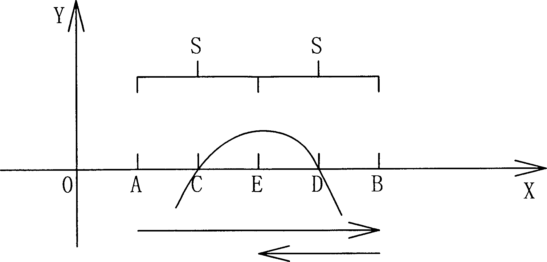
[0034] (1) Establish a section of detection interval A to B. This interval is centered on the theoretically optimal position of the lens during design, with a left and right offset of S distance, and S is taken as 0.25mm.

[0035] (2) At the beginning, the lens is placed at position A, and after the computer sends an instruction to start commissioning, the controller receives the instruction to drive the actuator to move the lens from one end A of the interval to the other end B, point by point during the movement of the lens Test a group of optical parameters a(x), b(x), c(x), d(x), ... related to the position of the lens, and record the test data. After the lens reaches B, the computer will record the test data according to The pre-established mathematical model y=f[a(x), b(x), c(x), d(x), ...] calculates and ju...

Embodiment 2

[0038] Embodiment two: see attached figure 1 and Figure 6 As shown, a method for determining the best position of the lens in the scanning head, its content is:

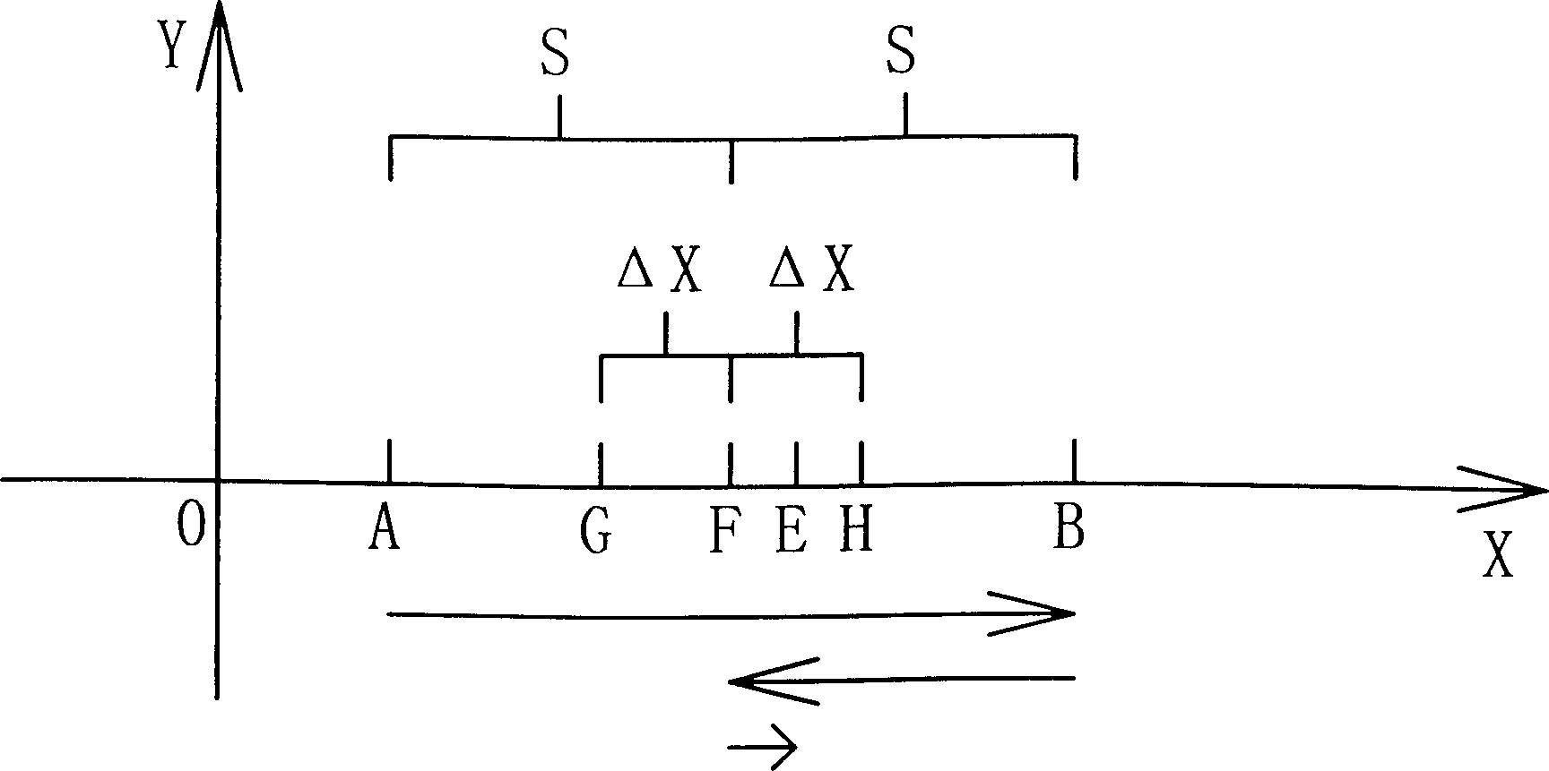
[0039] After the camera lens is moved to the best point E position by the method of embodiment one, in order to confirm the reliability of the lens adjustment position, test again and judge whether it is the best point, if the answer is, then the positioning ends the adjustment; if not, the computer sends command, make the actuator take the F point position when it stops as the center, and search for the best point E position in the interval GH with a left and right offset of Δx. After finding it, it will locate at this point. image 3 . Others are the same as the method in Embodiment 1.

Embodiment 3

[0040] Embodiment three: see attached figure 1 , a method for determining the optimal position of the lens in the scanning head, its content is:

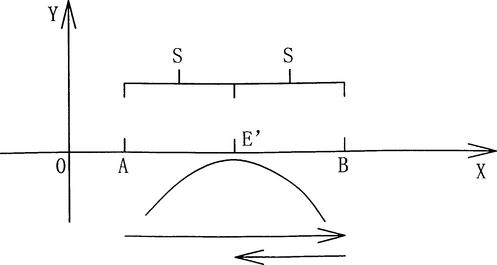
[0041] (1) Establish a section of detection interval A to B. This interval is centered on the theoretically optimal position of the lens during design, with a left and right offset of S distance, and S is taken as 0.25mm.

[0042] (2) The minimum index value of y is set in advance; at the beginning, the lens is placed at position A, and after the computer sends an instruction to start commissioning, the controller receives the instruction to drive the actuator to move the lens from one end A of the interval to the other end B , test a set of optical parameters a(x), b(x), c(x), d(x), ... related to the lens position point by point during the lens movement, and calculate y=f[a(x) at the same time , b(x), c(x), d(x), ...] values, and compare and judge with the set minimum index value of y, when y≥the minimum index appears for the fir...


PUM


Abstract

A method for determining the optimal position of lens in scan head includes choosing a test region from A to B, whose center is the theoretic optimal position, moving lens from A to B while measuring and recording the optical parameters associated with said optimal position point by point, and calculating the optimal position of lens according to a mathematicla model. Its advantages are high speed, accuracy and reliability.

Description

technical field [0001] The invention relates to an automatic optical mechanism adjustment (Auto-OMA) method of a scanning head in the manufacturing process of a scanner, in particular to a method for adjusting the optimal optical position of a lens (Lens) on the scanning head relative to a charge-coupled device (CCD / B). This method mainly studies how to find the best optical position and how to adjust the lens to the best optical position in automatic lens adjustment. Background technique [0002] The scanning head is the core of the photoelectric conversion mechanism of the scanner. It is mainly composed of an optical head frame, a lens (Lens) and a charge coupler (CCD / B). When assembling, the lens is inserted into the lens hole of the optical head frame, and the charge coupler ( CCD / B) is installed on the lens imaging position to form a photoelectric scanning component. The optical performance of the scanning head is not only related to each opti...

Claims


Application Information

Patent Timeline
Patent Type & Authority Applications(China)
IPC IPC(8): G02B26/10G02B27/62G06T7/00
Inventor 杜世丽曾斌
Owner 力捷电脑(中国)有限公司
Why Eureka
Try Eureka