Screw-less mainframe board fixing device

A motherboard and host technology, applied in the field of devices, methods and systems, capable of solving problems such as damage to the motherboard

Inactive Publication Date: 2003-03-12
富骅企业股份有限公司
View PDF0 Cites 3 Cited by
  • Summary
  • Abstract
  • Description
  • Claims
  • Application Information

AI Technical Summary

Problems solved by technology

If a consumer screwdriver slips, damage to the motherboard can be serious

Method used


Image

  • Screw-less mainframe board fixing device
  • Screw-less mainframe board fixing device
  • Screw-less mainframe board fixing device

Examples


Embodiment Construction

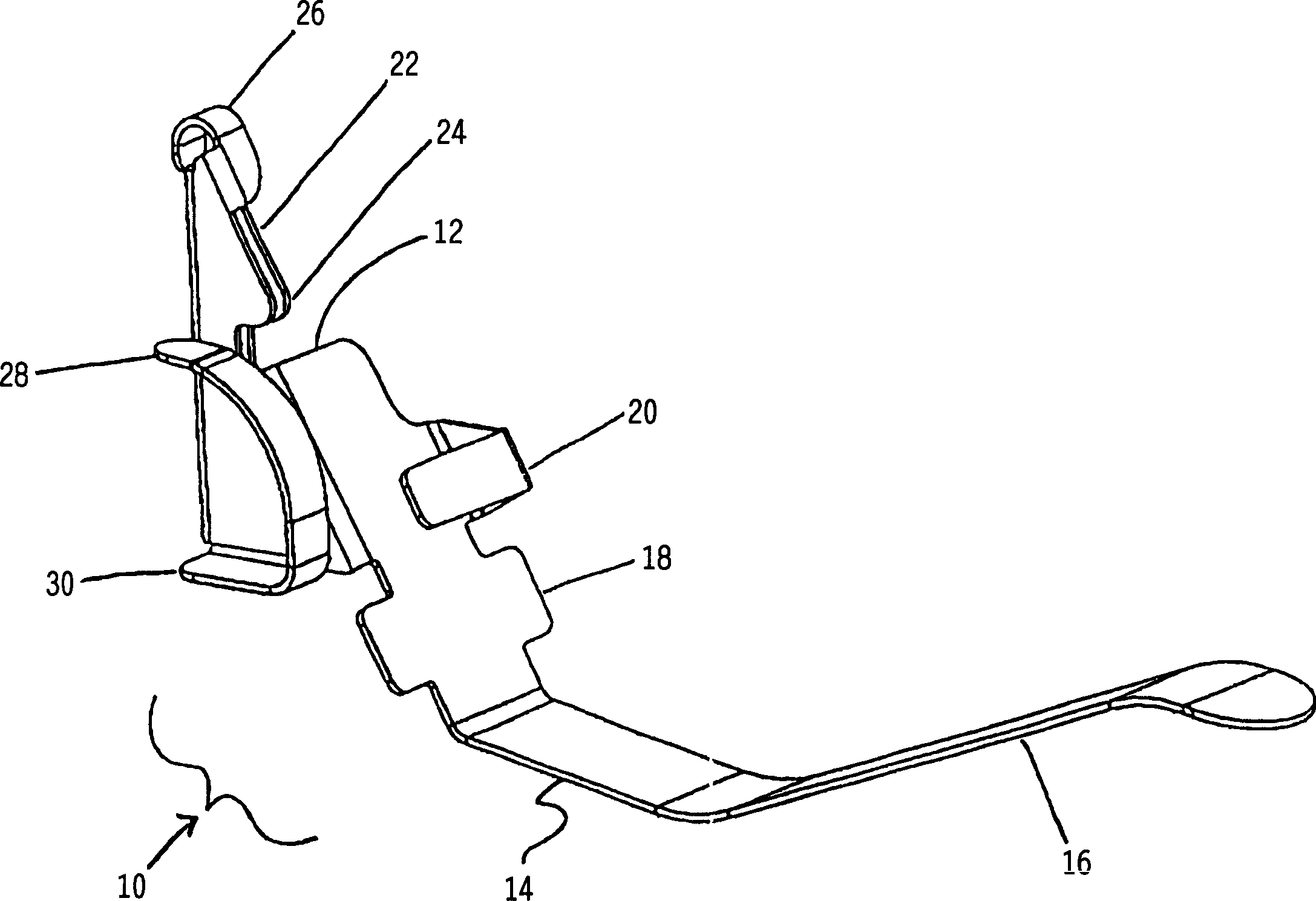
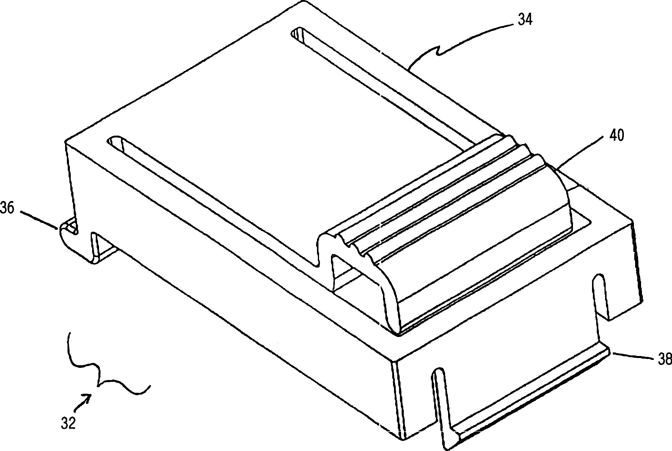
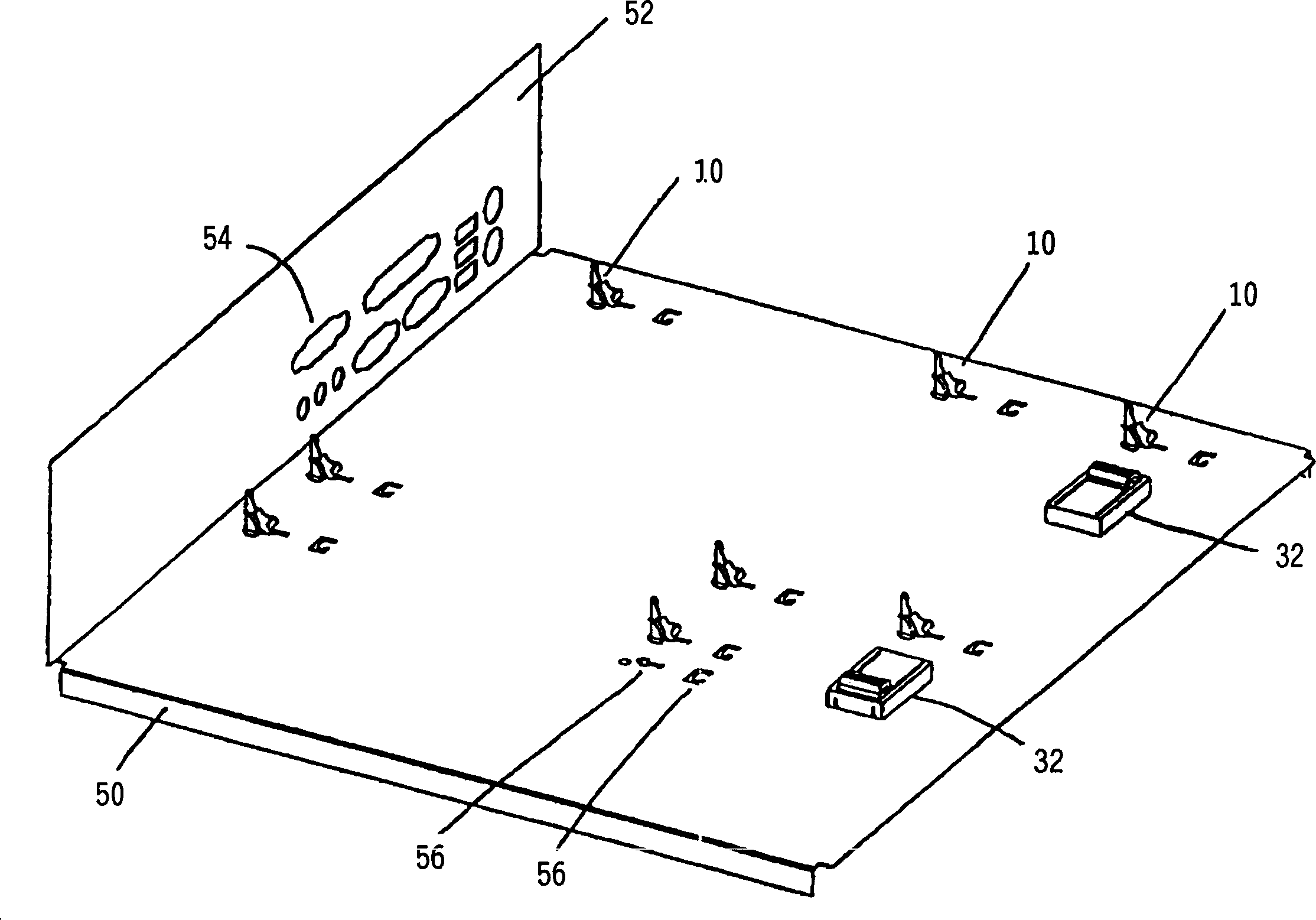
[0020] in Figure 1-Figure 8 Among them, the following components are involved: link 10, body 12, tail 14, spring 16, fulcrum 18, stop 20, head 22, hook 24, guide 26, ground arm 28, foot 30, retainer 32, retainer body 34 , Holding foot 36, holding adjustment member 38, board holding member 40, chassis 50, back plate 52, input and output slot 54, positioning body 56, main board 60 and hole 62

[0021] in figure 1 Among them, the connector 10 has a body 12. A body 12 has a tail 14 which may include a spring 16. The connecting piece 10 can be inserted into a specific position by the tail 14 and the spring 16, and in the computer chassis (such as image 3 Shown) is maintained. The spring 16 can help maintain and position the orientation (orientation) of the connector 10, which can make the motherboard (such as Figure 4-8 The installation shown) is more convenient.

[0022] The material selected for the connecting member 10 can improve the spring constant of the spring 16. The connec...


PUM


Abstract

A fixer for fixing motherboard without screw is composed of head part for matching with motherboard, a tail part for matching with bottom plate, and a spring part for forcing its head part to match with motherboard. Its fixing method includes arranging one or more said fixer on bottom plate, pivoting their tail parts to bottom plate, matching their head parts with the installation holes on motherboard, and detachably locking the motherboard and bottom plate.

Description

Technical field [0001] The present invention relates to a computer and a computer manufacturing method, and more particularly to a device, method and system, which can easily mount a motherboard on and electrically ground to a computer chassis. Background technique [0002] Computer manufacturers mainly rely on large manufacturing volumes (volume) to compete with other manufacturers in the same industry. Therefore, manufacturing technology must effectively utilize components and labor to produce competitive products. Each manufacturing step or component in computer assembly increases manufacturing costs, but cannot lead to increased profits. For example, when mounting a motherboard on a chassis, multiple components and multiple manufacturing steps are usually required. [0003] The motherboard is usually mounted on the chassis with screws, which pass through the standard pattern of screw holes. Each screw must be installed into a threaded metal standoff through the motherboard ho...

Claims


Application Information

Patent Timeline
Patent Type & Authority Applications(China)
IPC IPC(8): H01R4/48H01R4/66H05K7/14
CPCH05K7/142H01R4/66H01R4/4881
Inventor 保罗·R·胡珀
Owner 富骅企业股份有限公司
Why Eureka
Try Eureka