Reactor control-rod driving mechanism with adjustable magnetic damper

A driving mechanism and magnetic damper technology, applied in the control of nuclear reactions, reactors, climate sustainability, etc., can solve the problems of long transmission chain, scratches, sensitivity, etc., to increase the damping arm, simple processing and manufacturing, Stable and reliable transmission effect

Inactive Publication Date: 2003-03-26
TSINGHUA UNIV
View PDF0 Cites 19 Cited by
  • Summary
  • Abstract
  • Description
  • Claims
  • Application Information

AI Technical Summary

Problems solved by technology

However, during the process of manufacturing and operation, it was found that the existing control rod drive mechanism has the following problems: ①The magnetic damper participates in the transmission, which makes the transmission chain of the entire drive mechanism relatively long, which is not conducive to its smooth operation; ②The structure of the drive mechanism bracket is complex , the processing is difficult to meet the design accuracy requirements; ③The magnetic damper is located inside the drive mechanism bracket, and its radial dimension is limited. The torque is extremely sensitive to this gap value, and small manufacturing and assembly errors will cause a large change in the falling speed of the rod, and sometimes even "scratch" between the moving disk and the magnetic disk, resulting in stuck rods; ④ When the falling speed is due to processing, assembly When the error does not meet the design requirements, effective adjustment cannot be performed

Method used


Image

  • Reactor control-rod driving mechanism with adjustable magnetic damper
  • Reactor control-rod driving mechanism with adjustable magnetic damper
  • Reactor control-rod driving mechanism with adjustable magnetic damper

Examples


Embodiment Construction

[0011] The present invention will be further described in detail below in conjunction with the accompanying drawings.

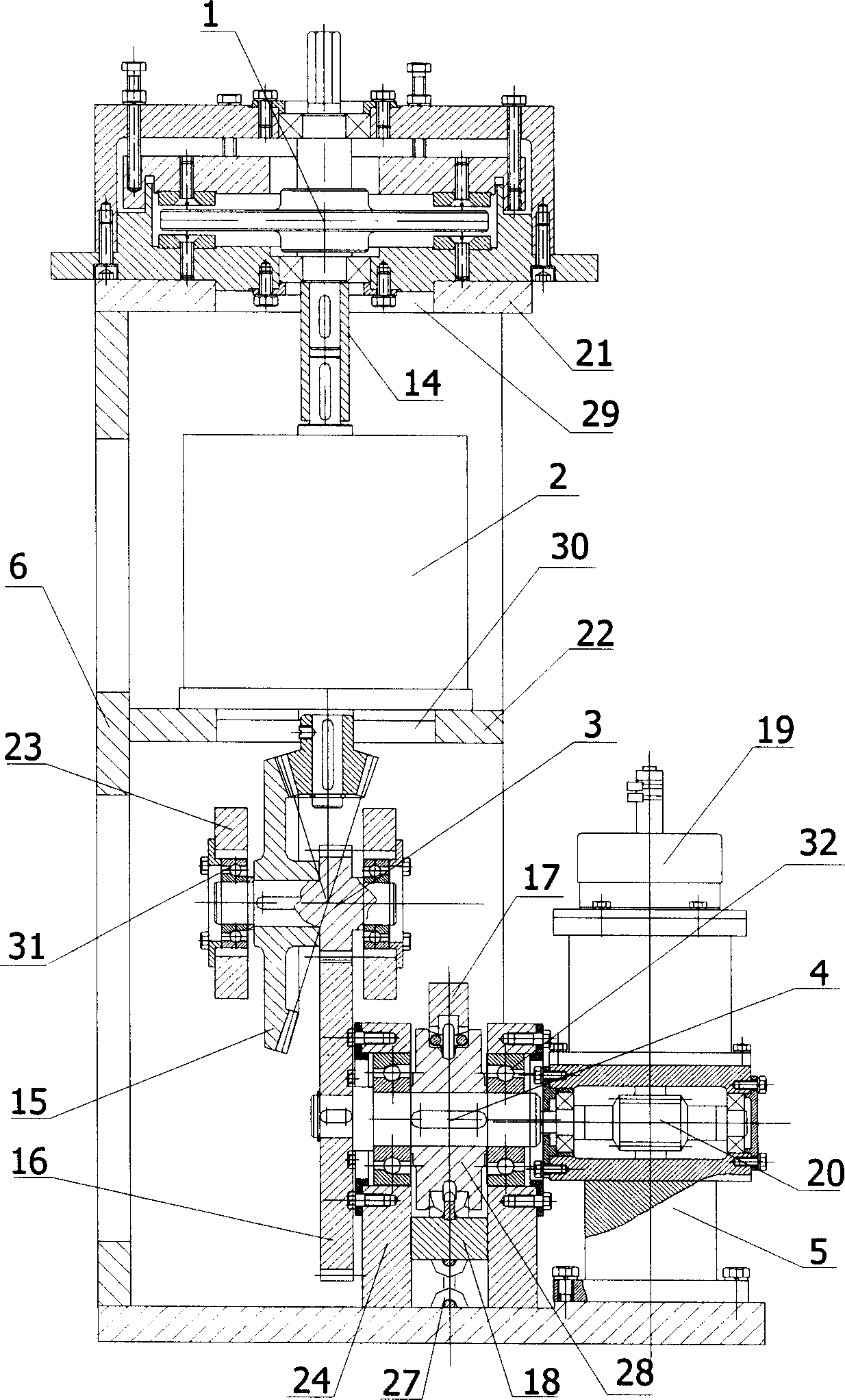
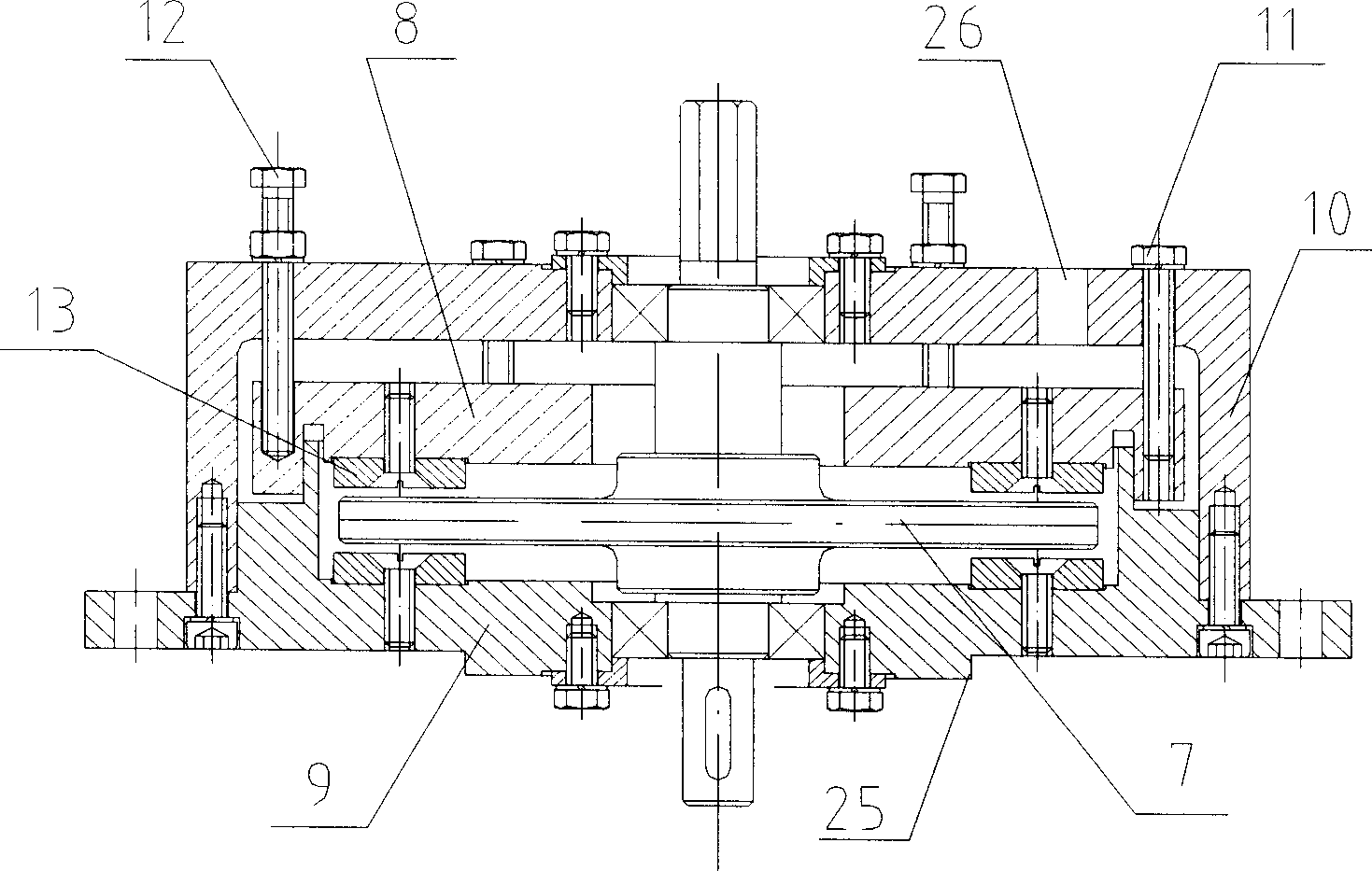
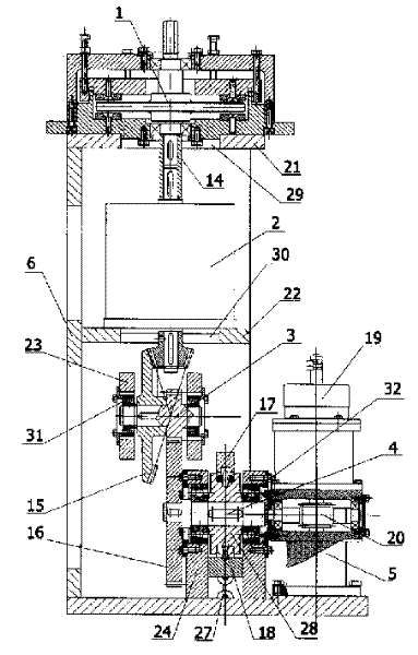
[0012] The reactor control rod drive mechanism with an adjustable magnetic damper provided by the present invention consists of an adjustable magnetic damper 1, a motor 2, a gear reduction mechanism 3, a sprocket device 4, a rod position measurement system 5 and a drive mechanism bracket 6 and other parts. The adjustable magnetic damper 1 includes: a moving disk 7, an upper disk 8, a lower disk 9, an upper bearing seat 10, an adjusting screw 11, a locking screw 12, a magnetic block 13 and the like. The magnetic damper 1 is installed on the outer top of the driving mechanism, and is connected with the motor 2 by a shaft sleeve 14 . In order to make the structure of the magnetic damper more compact, not only samarium cobalt permanent magnet material Sm is housed on the lower disk 9 2 (Co, Cu, Fe, Zr) 17 The magnetic block 13 made is also equipped with a bear...


PUM


Abstract

The drive mechanism comprises the drive mechanism bracket, the driving chain, the system for measuring the position of the rod and the magnetic damper. The driving chain consists of the motor, the gear reduction mechanism and the chain wheel. The magnetic champer comprises the moving disc, the upper and lower magnetic discs and the bearing seat. Since playing the damping function only without the driving function as well as the adjustable structure, the magnetic damper provides the features of shorter driving chain, smooth reliable driving and large enough brake moment. Said mechanism reduces the influence of the precision of manufacturing and assembling the control rod driving mechanism on the rod drop as well as eliminates the 'scraping' between the moving disc and the magnetic disc.

Description

technical field [0001] The invention relates to a driving device for reactor control rods, in particular to a control rod driving mechanism with a magnetic damper. Background technique [0002] Under normal reactor conditions, the control rod drive mechanism drives the control rods to move in the reactor at a certain speed, adjusts the reactivity of the core, and realizes normal reactor startup, power regulation and shutdown; under reactor accident conditions, the control rods The drive mechanism is powered off, and the control rods are quickly inserted into the core by their own weight to realize emergency shutdown of the reactor. The magnetic damper is the brake component used to limit the speed of the reactor accident rod drop. [0003] At present, control rod drive mechanisms with magnetic dampers are used in THTR reactors in Germany, HTTR reactors in Japan, and HTR-10 reactors designed and built by Tsinghua University. These driving mechanisms generally include compon...

Claims


Application Information

Patent Timeline
Patent Type & Authority Applications(China)
IPC IPC(8): G21C7/14
CPCY02E30/39Y02E30/30
Inventor 刁兴中周惠忠黄志勇吴元强吴宗鑫徐元辉曹丽杨念祖
Owner TSINGHUA UNIV
Why Eureka
Try Eureka