Water penetrating pipe with strip projected parts and connection methods

A connection method and permeable pipe technology, applied in the field of permeable pipes, can solve the problems of small drainage space, reduced bending resistance, and small drainage capacity of drainage grooves, and achieve high drainage capacity, enhanced longitudinal bending resistance, and increased The effect of seepage pressure difference

Inactive Publication Date: 2003-04-02
李兰英
View PDF0 Cites 7 Cited by
  • Summary
  • Abstract
  • Description
  • Claims
  • Application Information

AI Technical Summary

Problems solved by technology

In these drainage projects, a drainage core board with a drainage groove is commonly used, and the drainage board is composed of a permeable filter layer (such as figure 1 as shown, Picture 1-1 for figure 1 sectional schematic diagram), the disadvantage of this kind of drainage board is that under the external earth pressure or the pressure of other construction vehicles acting on the soil, the drainage channels between the drainage grooves are often compressed, such as Figure 1-2 As shown, the deeper the drainage board is buried, the greater the external load, the greater the compression, the smaller the drainage space of the drainage channel, and the smaller the drai

Method used


Image

  • Water penetrating pipe with strip projected parts and connection methods
  • Water penetrating pipe with strip projected parts and connection methods
  • Water penetrating pipe with strip projected parts and connection methods

Examples


Embodiment Construction

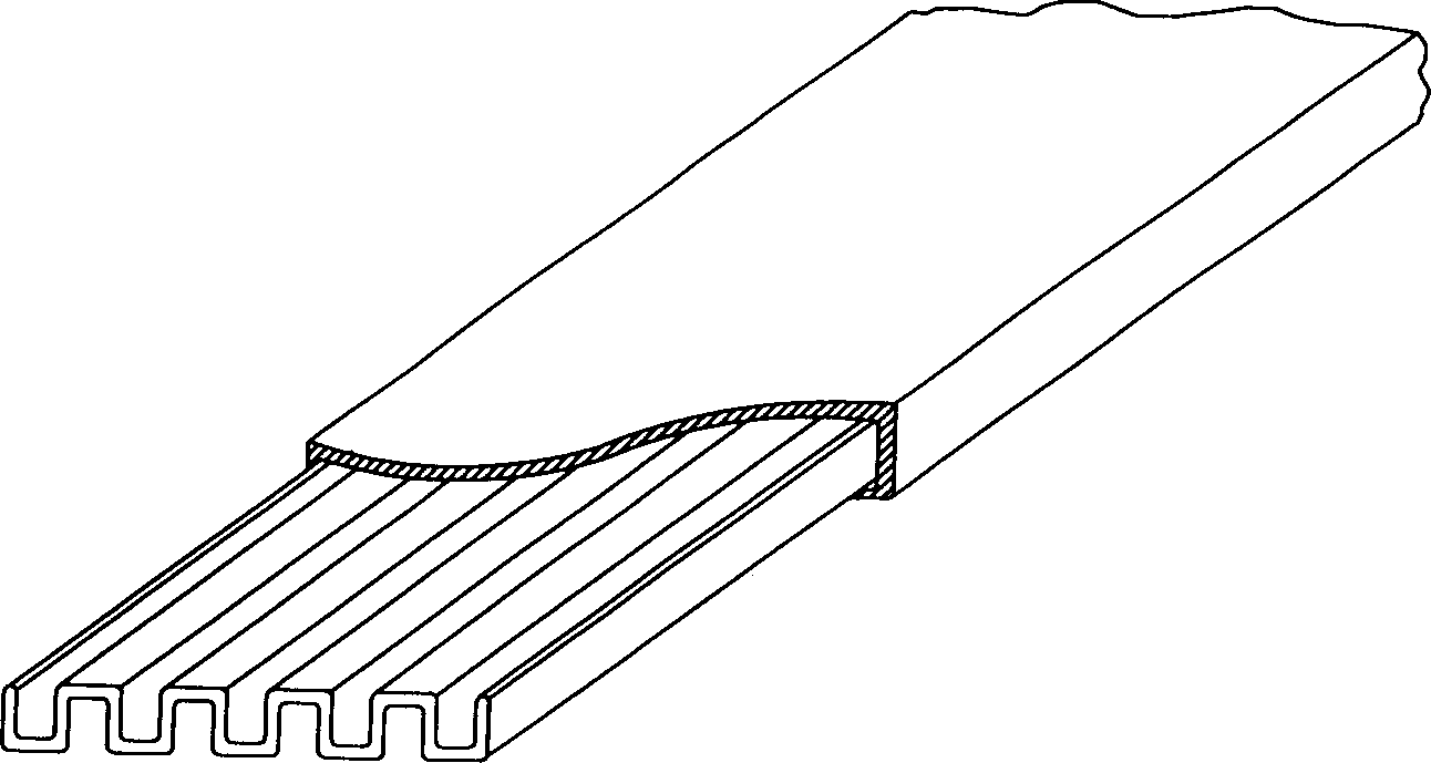
[0035] Such as image 3 , Figure 3-1 As shown, the present embodiment one includes a geotextile layer 5, a water permeable pipe 1 with a water permeable hole 2, and raised strips 3 perpendicularly intersecting the ring direction of the water permeable pipe. Drain grooves 4 are formed between the raised strips 3 . The permeable pipe 1 and the protruding strip 3 of this embodiment are both made of plastic PVC, the protruding strip 3 is welded on the outer wall of the permeable pipe 1 , and the geotextile 5 is bonded to the top surface of the protruding strip 3 . Only one layer of geotextile can be wrapped outside the strip-shaped protruding permeable pipe; multi-layer geotextile can also be wrapped according to needs, and the joints of adjacent layers of geotextiles are staggered; Under the premise that part of the area of ​​the permeable pipe is permeable, a layer of geomembrane is installed on the remaining area. The above PVC permeable pipe 1 is extruded by an extruder, a...


PUM


Abstract

A pervious pipe for dewatering from soft foundation, soil, or earth structure is composed of the osmotic filer layer and the pipe with pervious holes or slits, and features that on said pipe there are convex strips for forming the drainage channels between adjacent convex strips. Its advantages are high water permeability and high dewatering efficiency.

Description

1) Technical field [0001] The invention relates to a permeable pipe for eliminating water seepage. Two), background technology [0002] At present, in civil and agricultural projects, it is often necessary to drain the interior of soil or structures, such as lowering the groundwater level, intercepting and draining groundwater, and drainage of soft foundations. In these drainage projects, a drainage core board with a drainage groove is commonly used, and the drainage board is composed of a permeable filter layer (such as figure 1 as shown, Picture 1-1 for figure 1 sectional schematic diagram), the disadvantage of this kind of drainage board is that under the external earth pressure or the pressure of other construction vehicles acting on the soil, the drainage channels between the drainage grooves are often compressed, such as Figure 1-2 As shown, the deeper the drainage board is buried, the greater the external load, the greater the compression, the smaller the drainag...

Claims


Application Information

Patent Timeline
IPC IPC(8): E02D19/20
Inventor 李兰英
Owner 李兰英
Why Eureka
Try Eureka