Cyclic element of rolling bearing

A technology of ring elements and rolling bearings, which is applied in the direction of bearing elements, rolling contact bearings, rotating bearings, etc., and can solve problems such as high noise

Inactive Publication Date: 2003-04-09
SKF IND SPA
View PDF3 Cites 6 Cited by
  • Summary
  • Abstract
  • Description
  • Claims
  • Application Information

AI Technical Summary

Problems solved by technology

Rapid wear of the plastic due to relative rotation between the plastic and steel rubbing agai...

Method used


Image

  • Cyclic element of rolling bearing
  • Cyclic element of rolling bearing
  • Cyclic element of rolling bearing

Examples


Embodiment Construction

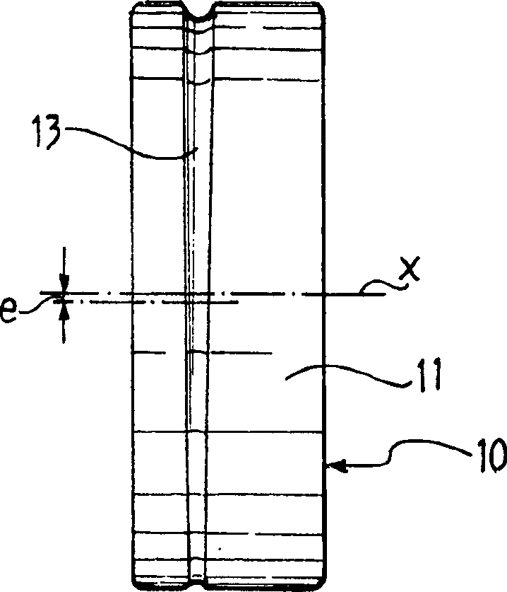
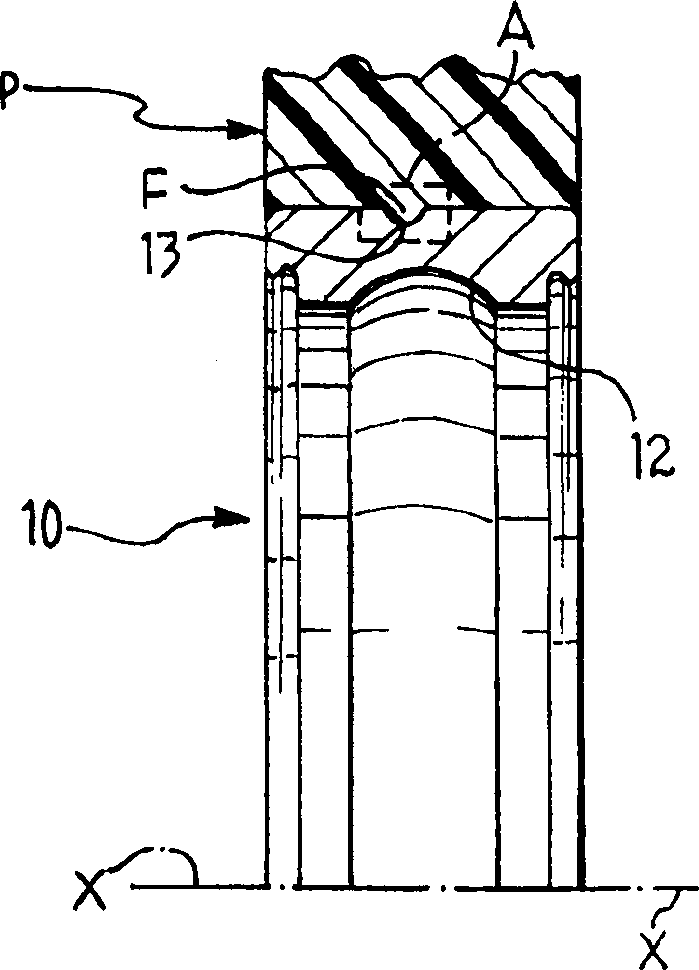
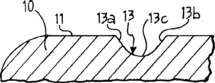
[0015] first reference figure 1 , the annular element constituting a radially outer ring of a rolling bearing is denoted as 10 . The ring element 10 has an outer cylindrical surface 11 and a raceway 12 on its inner surface.

[0016] In this description and claims, terms and expressions indicating position and orientation (eg “radial”, “axial”, “inner”, “outer”) are intended to be relative to the central axis x of the ring element 10 .

[0017] Such as figure 2 with 6 As shown, a body P of plastics material is molded on the outer cylindrical surface 11 and constitutes a fixed housing supporting the support. The body P of plastics material may be a supporting element installed in the washing machine so as to rotatably support via the bearing a rotating shaft on which the drum of the washing machine is fixed. In general, reference to this possible field of application should not be construed as limiting the scope of the invention in any way. For example, the ring element 10...


PUM


Abstract

An annular element (10) for a rolling bearing comprises a cylindrical surface (11) around the circumference of which a groove (13), the radial and axial depth of which are variable around the circumference, is formed. The cylindrical surface is suitable for being over-moulded with a plastics material to form a body (P) which is fixed firmly for rotation with the annular element (10) and has a plastics projection (F) complementary with the groove (13). The projection (F) can cooperate with the groove to prevent relative rotation between the annular element (10) and the body (P).

Description

technical field [0001] The invention relates to an annular element for a rolling bearing of the type comprising a cylindrical surface in which is formed a groove of variable radial depth around the circumference of the cylindrical surface, the surface being suitable for molding with The plastic material thereon forms a body fixed for rotation with the ring and having a groove complementary to and adapted to cooperate with the groove in order to prevent relative rotation between the ring and the plastic body. plastic protrusions. Background technique [0002] Ring elements of the above-mentioned type are known, for example, from EP-A-0972958, US-A-3832024, and US-A-4925322. These publications describe bearings having a ring with eccentric grooves of rectangular axial section. [0003] A disadvantage that arises when a plastic body is molded onto the ring element of a rolling bearing is that due to the different coefficients of thermal expansion of steel and plastic, the pla...

Claims


Application Information

Patent Timeline
IPC IPC(8): D06F37/00F16C27/06F16C35/077
CPCF16C35/077Y10S384/903F16C27/066D06F37/00F16C33/586F16C19/06F16C35/063F16C35/067F16C2340/00F16C2226/30
Inventor G·派罗尼F·加卢茨
Owner SKF IND SPA
Why Eureka
Try Eureka