Method for controlling DC-DC converter

A control method, DC-DC technology, applied in control/regulation systems, output power conversion devices, conversion equipment without intermediate conversion to AC, etc., can solve the problems of power supply circuit efficiency reduction, etc. The effect of reverse flow

Inactive Publication Date: 2003-04-09
SANYO ELECTRIC CO LTD
View PDF0 Cites 12 Cited by
  • Summary
  • Abstract
  • Description
  • Claims
  • Application Information

AI Technical Summary

Problems solved by technology

However, when the gap between the output voltage (n+1)Vdd of the DC-DC converter and the required output voltage is large, there is a problem that the efficiency of the power supply circuit is reduced.

Method used


Image

  • Method for controlling DC-DC converter
  • Method for controlling DC-DC converter
  • Method for controlling DC-DC converter

Examples


Embodiment Construction

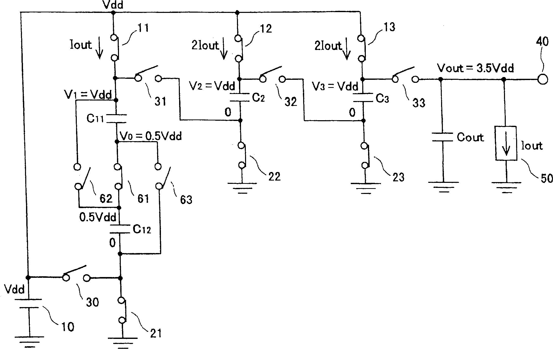
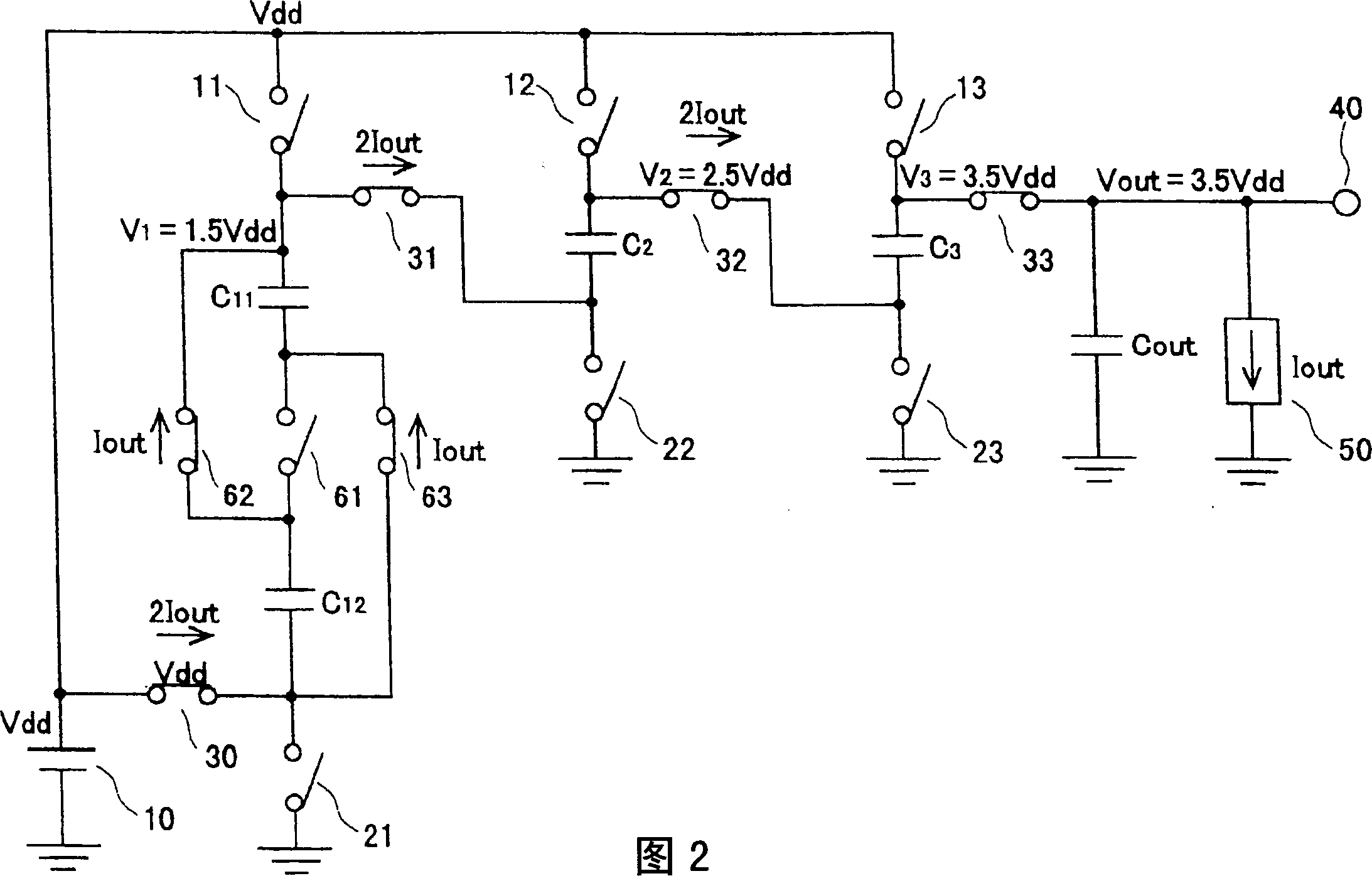
[0031] In the following, various embodiments of the present invention will be described in conjunction with the accompanying drawings. figure 1 2 is a circuit diagram showing a switched capacitor DC-DC converter with a three-stage structure of the first embodiment.

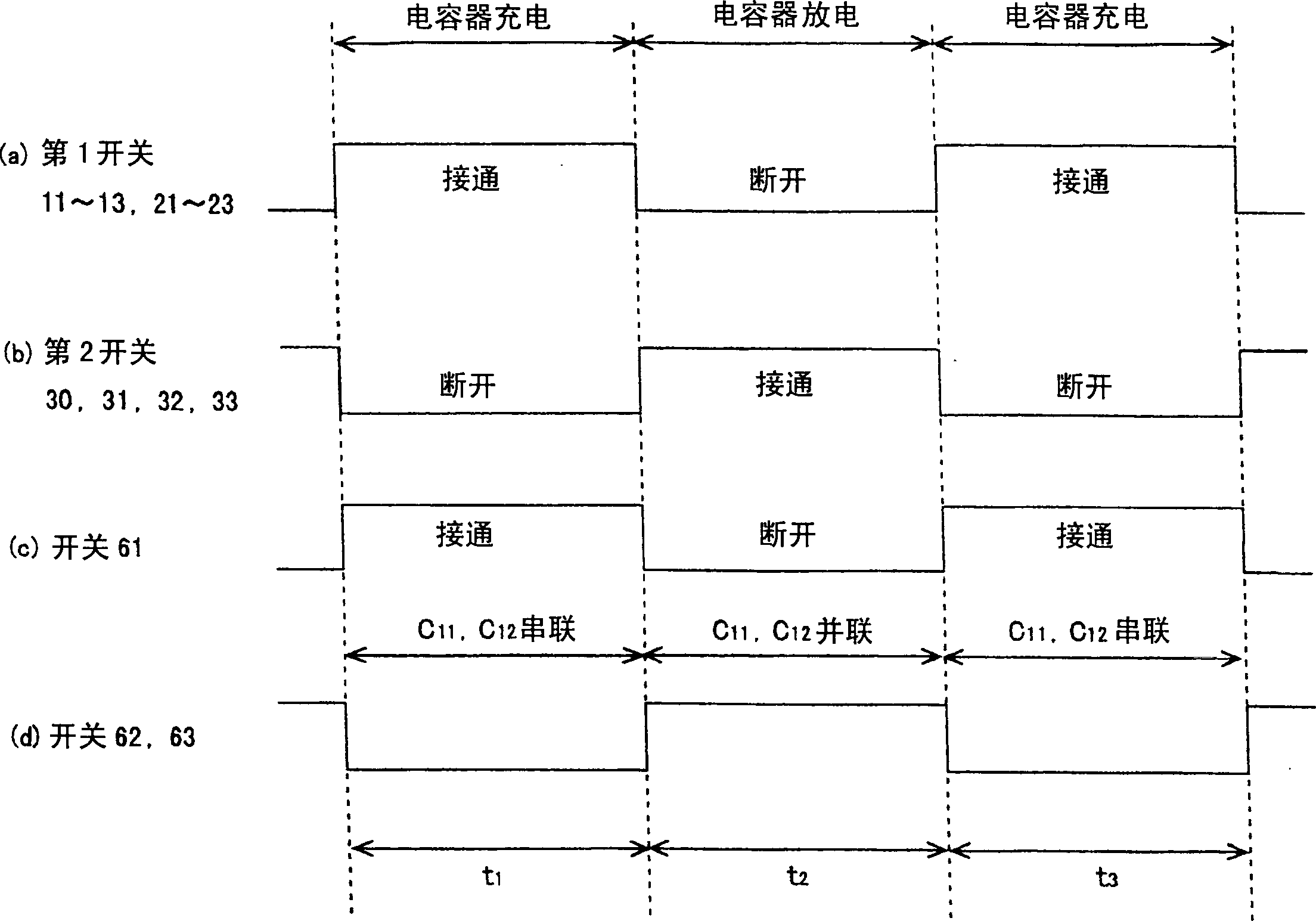
[0032] 10 is a voltage source for supplying a power supply voltage Vdd. C11 and C12 are capacitors that can be switched to be connected in series or in parallel through series-parallel switchover switches 61 , 62 and 63 . When the switch 61 is on and the switches 62, 63 are off, the capacitors C11, C12 are connected in series with each other. Conversely, when the switch 61 is off and the switches 62, 63 are on, the capacitors C11, C12 are connected in parallel with each other. Hereinafter, capacitors C11 and C12 having such a structure are referred to as series-parallel capacitors.

[0033] 11 is a switch provided between the power supply voltage Vdd and one end of the capacitor C11, and 21 is a switch provide...


PUM


Abstract

A method for controlling a DC-DC converter, which generates a step output voltage smaller than the source voltage Vdd, comprises three-section-switch-condenser structure for receiving the source voltage. The first section comprises two condensers C11, C12 and switches 61, 62, 63 for changing the condensers C11, C12 into series connection or parallel connection. During charge time, the switch 61 is turned on to connect the condensers C11, C12 into a series connection. During discharge time, the switches 62, 63 are turned on to connect the condenser C11, C12 into a parallel connection. In this way, 3.5Vdd step-up voltage can be obtained through the output terminal 40.

Description

technical field [0001] The invention relates to a control method of a DC-DC converter suitable for a power supply circuit, especially a control method of a DC-DC converter with high efficiency. Background technique [0002] In recent video equipment such as video cameras, digital still cameras (DSC), and DSC phones, CCDs (Charge Coupled Devices) for acquiring desired images have been adopted. The CCD drive circuit used to drive the CCD requires a power supply circuit that has positive and negative high voltages (a dozen V) and can provide a large current (several mA). Today, this high voltage is generated with switching regulators. [0003] Switching regulators can generate high voltages with high performance, that is to say with high efficiency (output power / input power). However, because this kind of circuit has the disadvantage of generating high-order harmonic noise when switching current, it is necessary to take shielding measures for the power circuit. Furthermore, ...

Claims


Application Information

Patent Timeline
Patent Type & Authority Applications(China)
IPC IPC(8): H02M3/135H02M3/07
CPCH02M3/07H02M2003/072H02M3/072H02M3/135
Inventor 名野隆夫
Owner SANYO ELECTRIC CO LTD
Why Eureka
Try Eureka