
Method of producing super low carbon steel using vacuum degassing

An ultra-low carbon steel, vacuum degassing technology, applied in the field of vacuum refining, can solve the problem of reduced decarburization capacity, and achieve the effect of improving decarburization performance, reducing rolling, and saving investment in equipment renovation

Inactive Publication Date: 2003-04-16
武钢集团有限公司
View PDF0 Cites 10 Cited by
  • Summary
  • Abstract
  • Description
  • Claims
  • Application Information

AI Technical Summary

Problems solved by technology

[0004] The purpose of the present invention is to provide a new method for vacuum degassing to produce ultra-low carbon steel, which can overcome the deficiencies of the above-mentioned technologies. This method can produce carbon content less than 15ppm simply and stably without modifying existing equipment. Ultra-low carbon steel to solve the problem of reduced decarburization ability during the corrosion process during the furnace service period

Method used


Image

  • Method of producing super low carbon steel using vacuum degassing
  • Method of producing super low carbon steel using vacuum degassing
  • Method of producing super low carbon steel using vacuum degassing

Examples


Embodiment Construction

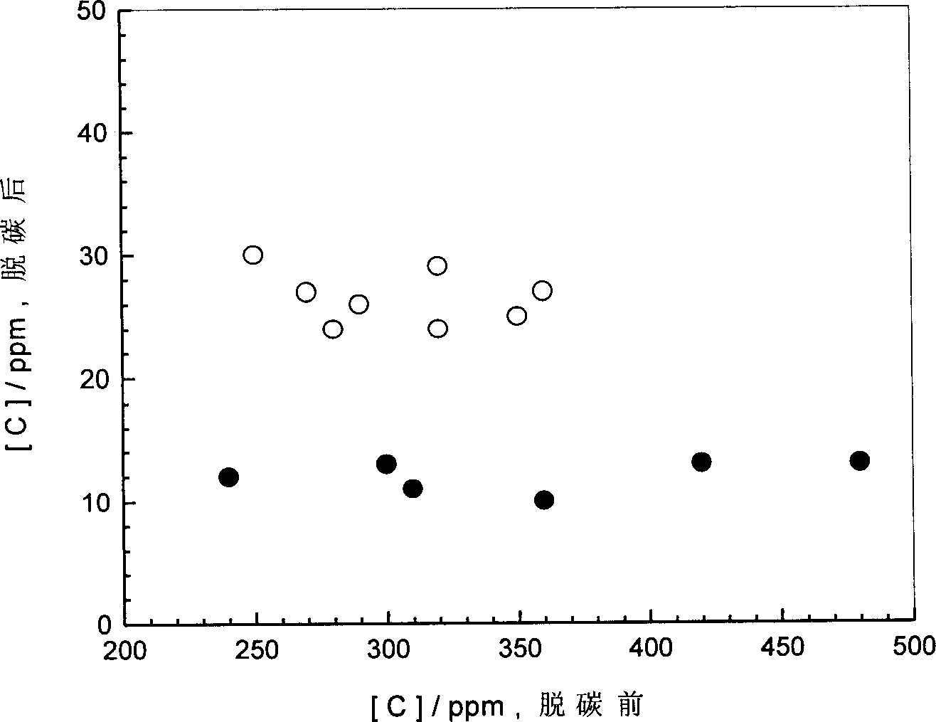
[0019] The decarburization operation using the method of the present invention is shown in Table 1, and the decarburization operation of the comparative example is shown in Table 2. The actual capacity of the ladle molten steel in the treatment process is 78t.

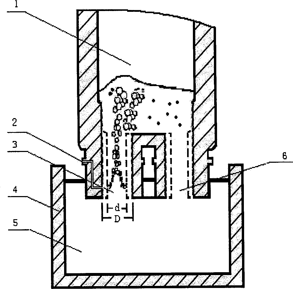
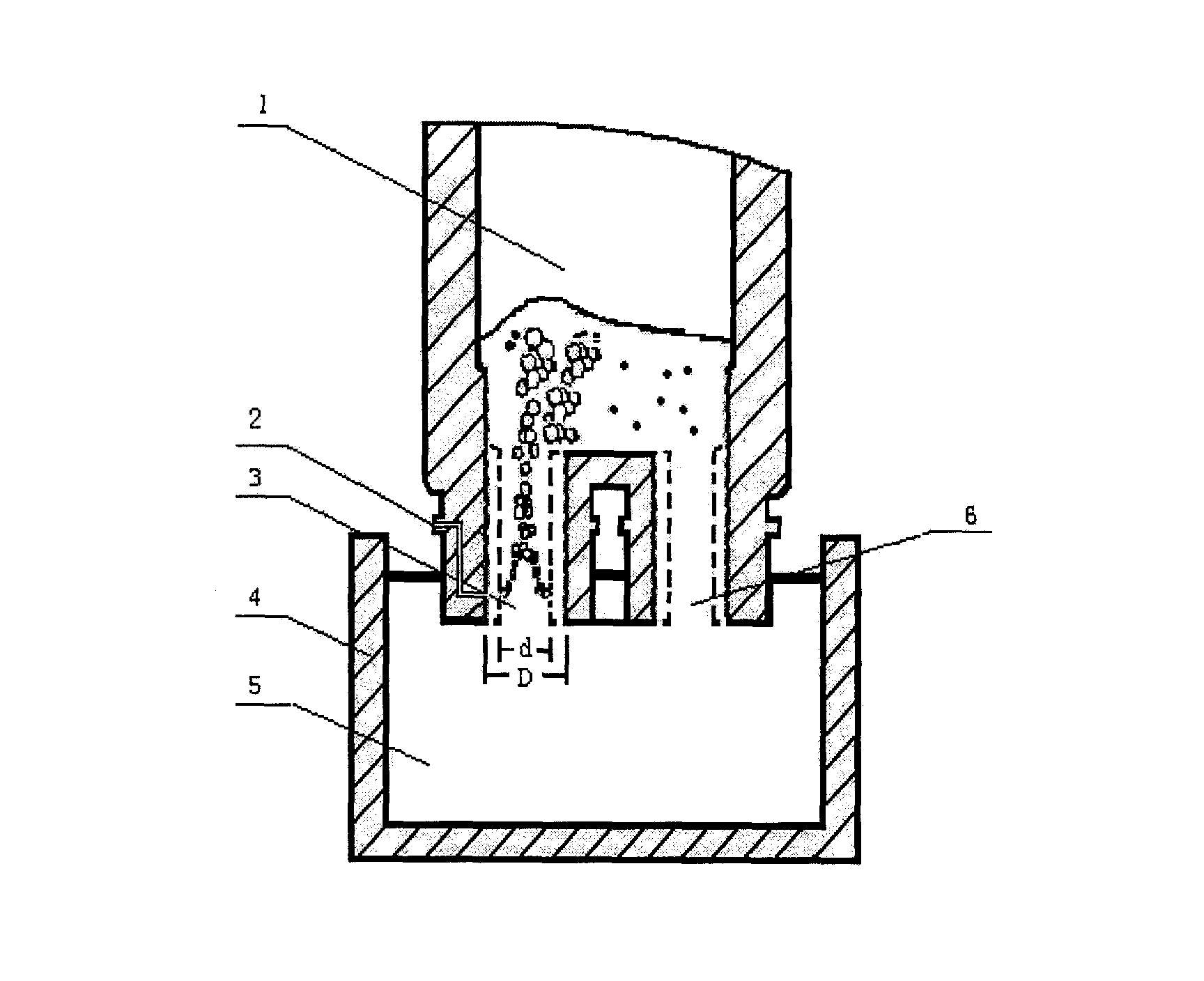
[0020] During the decarburization process, connect the insertion tube of the vacuum chamber ①, the ascending pipe ③ and the descending pipe ⑥, and simultaneously immerse in the molten steel ⑤ of the ladle ④ to draw a vacuum, and continuously inject argon gas from the conduit ② to drive the circulation of the molten steel for decarburization.

[0021] Furnace service period

Increase argon flow Nl / min·t

Vacuum

decarburization time

First 20 furnaces

≤9min >9min

10min

15min

5.2 6.4

≤0.2kPa

After 20 furnaces

10min

8min

15min

5.2 7~7.2 7.7~9

≤0.2kPa

[0022] Furnace service ...


PUM


Abstract

A process for preparing ultralow-carbon steel by vacuum degassing features that the argon flow and the vacuum level are dependent on the service age of the furnace, that is, for the initial 20 batches, the argon flow is matched with inner diameter of insertion-in tube, and for the following batch whose decarbonizing time is longer than 5 min, the argon flow is increased by more than 20%. Before decarbonizing the molten steel, the vacuum chamber is depressurized in advance. Within 0-10 min after beginning decarbonization, the depressurizing speed is increased.

Description

technical field [0001] The invention relates to a method for producing ultra-low-carbon steel by vacuum degassing, in particular to a method for producing ultra-low-carbon steel with carbon content less than 15ppm by using RH vacuum degassing equipment, and belongs to the field of vacuum refining. Background technique [0002] At present, iron and steel enterprises generally use vacuum degassing treatment to produce ultra-low carbon steel. In order to improve the decarburization production efficiency of this type of steel, technicians have proposed various methods. For example, when a steel factory uses the RH vacuum degassing equipment imported from Germany to produce ultra-low carbon steel, in the decarburization process of each furnace in the whole furnace service, the input of the gas conduit installed in the insertion pipe and the initial design inner diameter of the insertion pipe Matching argon gas flow, but the disadvantage of this operation method is that after a ce...

Claims


Application Information

Patent Timeline
Patent Type & Authority Applications(China)
IPC IPC(8): C21C7/10
Inventor 区铁喻承欢杨杰柳志敏徐静波应风晔彭林冯军陈清泉张汉平
Owner 武钢集团有限公司
Learn More