Connector having dust proof cover

A dust-proof cover and connector technology, applied in the direction of the base/shell, etc., can solve the problems of not being completely dust-proof, increasing the cost, and inconsistent with the general specifications of the joint industry.

Inactive Publication Date: 2003-04-16
COREMATE TECH CO LTD
View PDF0 Cites 4 Cited by
  • Summary
  • Abstract
  • Description
  • Claims
  • Application Information

AI Technical Summary

Problems solved by technology

[0011] 1. Refer to figure 1 , 4, 5, when the optical fiber cable terminal 2 is inserted into the second accommodation space 801 of the connector 8, the second accommodation space 801 must simultaneously accommodate the optical fiber cable terminal 2 and the The dust cover 9, therefore, causes the height h2 of the front end portion of the connector 8 (that is, the portion where the connector 8 can protrude through the mounting hole 601) to be greater than the height h1 of the connector 4 of the optical fiber connector 400 (This is the established general specification in the industry), and although the width w2 of the front end of the joint 8 is equal to the width w1 of the joint 4, this will cause the specification of the joint 8 to be inconsistent wit

Method used


Image

  • Connector having dust proof cover
  • Connector having dust proof cover
  • Connector having dust proof cover

Examples


Embodiment Construction

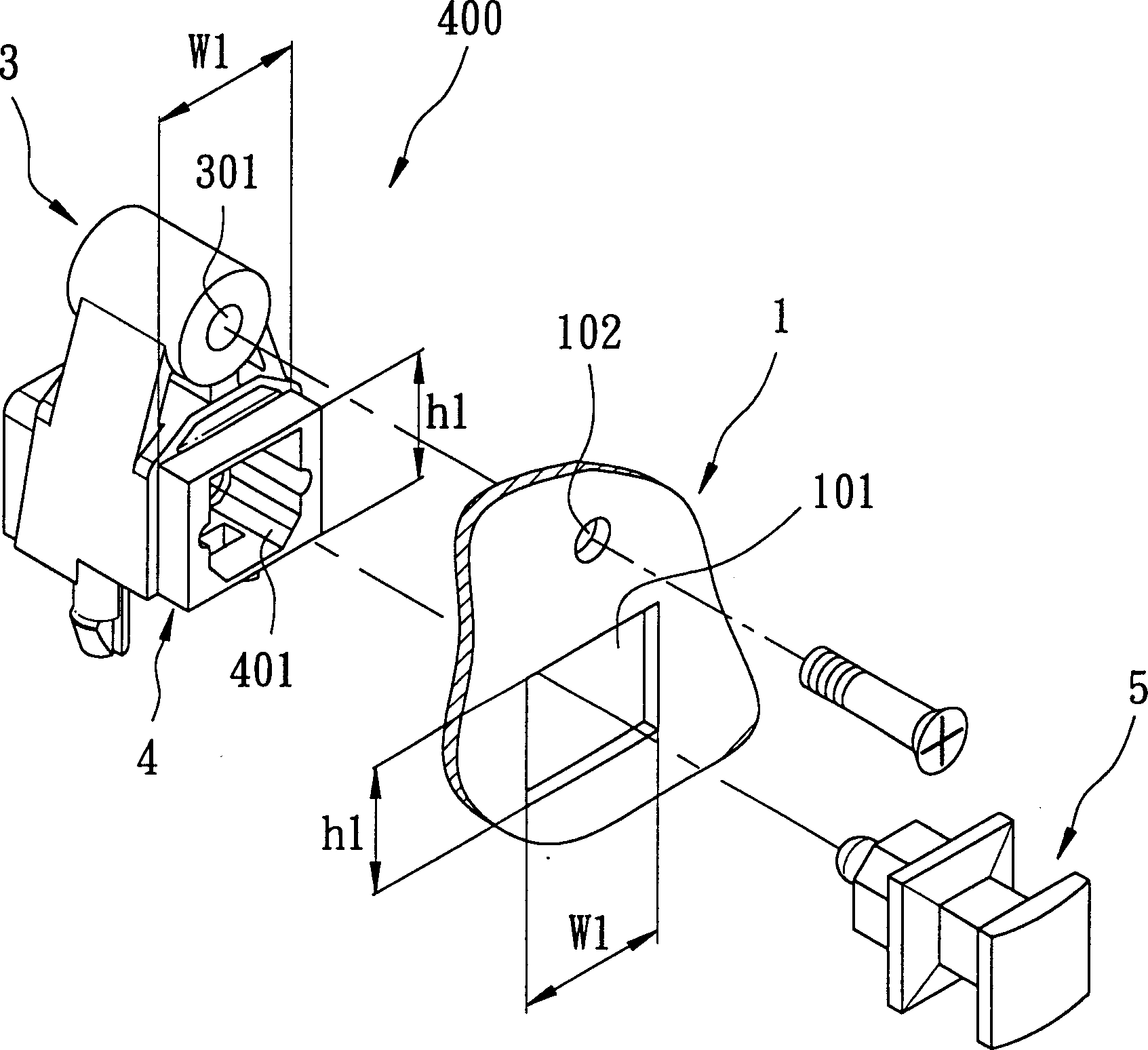
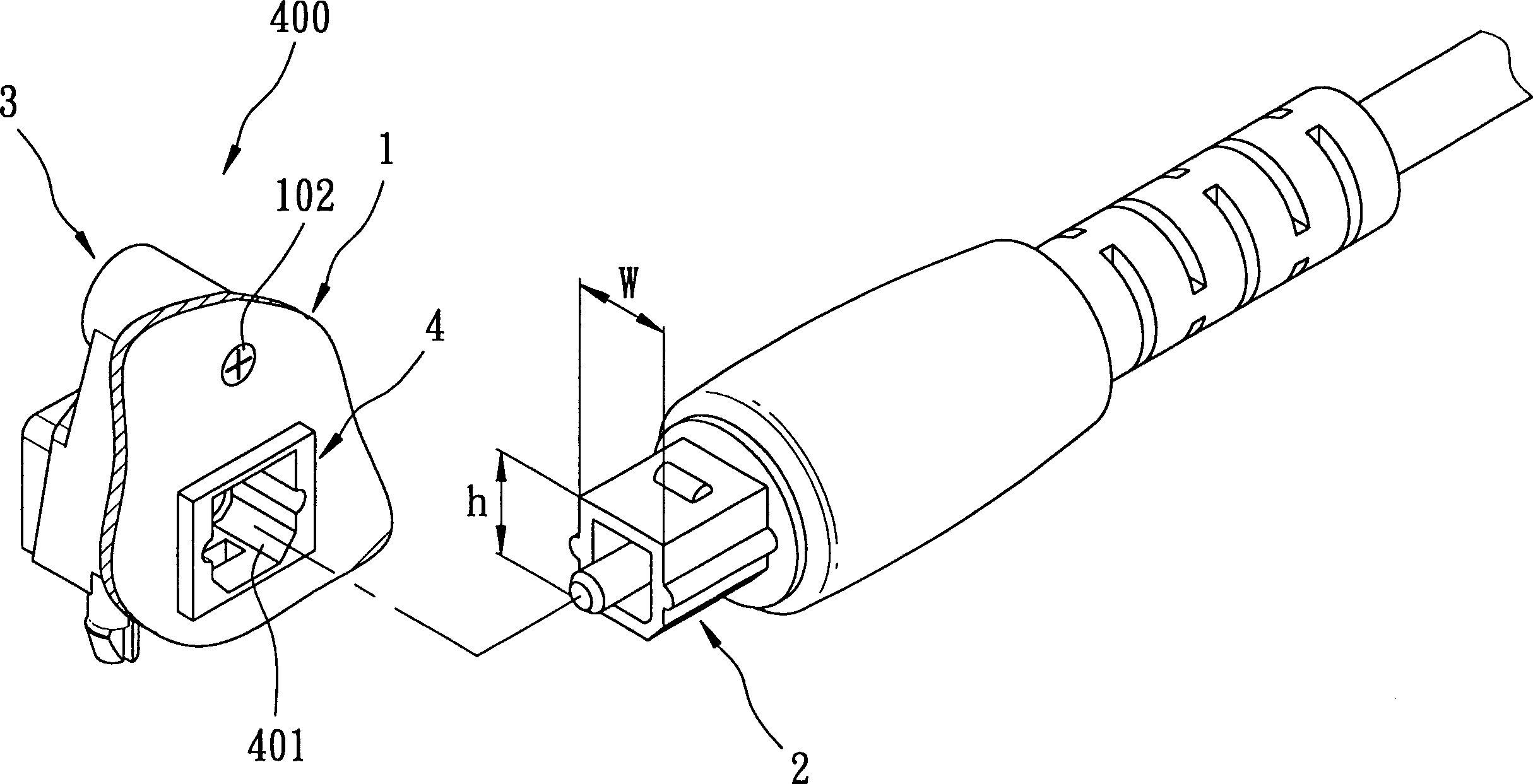
[0025] refer to Figure 6 , 8 , the connector 100 with dust cover of the present invention can be installed on a substrate 300 (the substrate 300 can be installed on a DVD player or a VCD player), and the connector 100 can be an optical fiber connection device for the insertion and positioning of the optical fiber cable terminal 2, the base plate 300 has a mounting hole 310, and a locking hole 320, the size of the optical fiber cable terminal 2 is a general standard established in the industry, the A preferred embodiment of the connector 100 includes: a housing 10 , a connector 20 , and a dust cover set 30 .

[0026] The casing 10 has a first accommodating space 11 with an opening facing forward, and a locking hole 12 .

[0027] The joint 20 is made of heat-resistant and wear-resistant high-hardness plastic material, and has a bottom wall 21, four side walls 22, 23, 24, 25 extending forward along the periphery of the bottom wall 21, and a The bottom wall 21 and the side wal...


PUM


Abstract

A connector with dust prevention cover includes a shell, a contact and a group of dust prevention covers, the said shell has a first containing space, the said contact has a second containing space and the said dust prevention cover group has a mounting plate, a dust preventing cover connected with the mounting plate, a positioning device and a cover clipping device, the said mounting plate can be clipped onto the side wall of the said contact with the help of the positioning device, and the mounting plate together with the contact can be inserted into the containing space. When the said mounting plate bends the dust prevention cover which will cover the open end of the second containing space, it can prevent dust from entering into the second containing space.

Description

【Technical field】 [0001] The invention relates to a connector, in particular to a connector with a dustproof cover. 【Background technique】 [0002] Such as figure 1 , 2 As shown, an existing optical fiber connector 400 can be installed on a substrate 1 (such as DVD player or VCD player) for insertion and positioning of an optical fiber cable terminal 2, the substrate 1 has a mounting hole 101, and A locking hole 102, the size of the optical fiber cable terminal 2 is a general specification established in the industry, its height is h, and its width is w. [0003] The optical fiber connector 400 includes a housing 3 , a joint 4 integrally protruding from the housing 3 , and a dustproof plug 5 . The housing 3 has a locking hole 301, and the joint 4 has an opening facing forward and corresponding to the shape of the optical fiber cable terminal 2, for the accommodation space 401 for the insertion of the optical fiber cable terminal 2, and the The size of the connector 4 mat...

Claims


Application Information

Patent Timeline
IPC IPC(8): H01R13/52
Inventor 王惠民
Owner COREMATE TECH CO LTD
Why Eureka
Try Eureka