Signal filtering method
A signal and signal output technology, applied in impedance networks, electrical components, multi-terminal-pair networks, etc., can solve problems such as non-standard component values, difficulty in obtaining transition band characteristics for RC filters, and increased manufacturing costs.
- Summary
- Abstract
- Description
- Claims
- Application Information
AI Technical Summary
Problems solved by technology
Method used
Image


Examples
Embodiment Construction
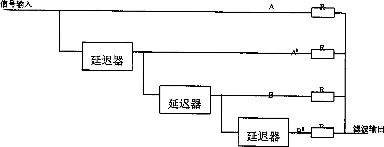
[0015] Fig. 1 is the circuit diagram of the embodiment. In the dotted box is the simplest set of filter form circuits.
[0016] As shown in Figure 1, this is the simplest form of a set of filtering with only two delayer outputs. Among them, the A output is equivalent to a "0" delay, and has the first delay relationship with the B output. It has a good filtering effect on the fundamental wave and odd harmonics of the width modulation signal. Followed by a π-type RC low-pass filter to filter out other high-order harmonic components.
[0017] Still taking the aforementioned demodulation of a pulse width modulation signal with a frequency of 600 Hz as an example, the structure and filtering effect of the invention will be described.
[0018] A is the usual pulse width modulation signal output, the frequency is 600Hz, and the period is 1639.3uS. The output of B is the pulse width modulation signal of A delayed by half cycle 819.65uS through the delayer. The delay here is easie...
PUM
 Abstract
Description
Claims
Application Information
 - R&D
- Intellectual Property
- Life Sciences
- Materials
- Tech Scout
- Unparalleled Data Quality
- Higher Quality Content
- 60% Fewer Hallucinations
Browse by: Latest US Patents, China's latest patents, Technical Efficacy Thesaurus, Application Domain, Technology Topic, Popular Technical Reports.
© 2025 PatSnap. All rights reserved.Legal|Privacy policy|Modern Slavery Act Transparency Statement|Sitemap|About US| Contact US: help@patsnap.com