Method for detecting position signal of switch reluctance machine
A technology of switched reluctance motor and detection method, which is applied in the direction of electronic commutator, etc., can solve problems such as misoperation of switched reluctance motor, and achieve the effect of stable control
- Summary
- Abstract
- Description
- Claims
- Application Information
AI Technical Summary
Problems solved by technology
Method used
Image
Examples
Embodiment Construction
[0009] Specific embodiments are given below in conjunction with the drawings to further illustrate how the present invention is implemented.
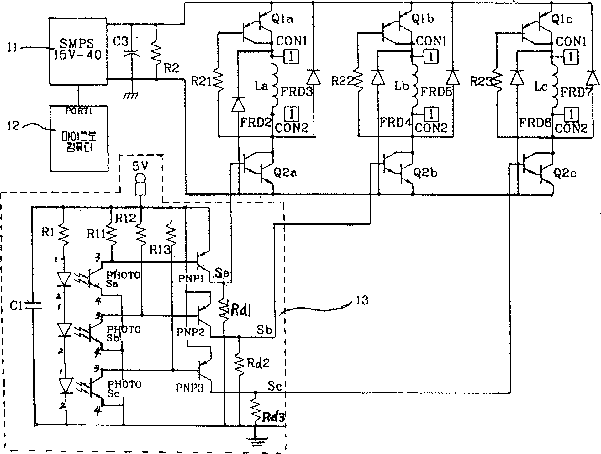
[0010] figure 1 It is a power supply circuit and drive circuit diagram of a switched reluctance motor with a general 6 / 4 structure. As shown in the figure, it has the following structure: a control power supply device 11 that sequentially applies voltage to the motor coil; and applies a signal to the control power supply device A microcomputer 12 that changes the voltage control between 15 volts and 40 volts; detects the position of the rotor in the motor, and outputs position sensors Sa, Sb, and Sc of the rotor position signal, and performs switching devices based on the above-mentioned rotor position signal The basic drive circuit 13 composed of PNP switching devices with on / off switching; the output interface of the computer 12 is connected to the power supply 11, the capacitor C1 and the resistor R 2 Connected in parallel, both ends a...
PUM
 Abstract
Description
Claims
Application Information
 - R&D
- Intellectual Property
- Life Sciences
- Materials
- Tech Scout
- Unparalleled Data Quality
- Higher Quality Content
- 60% Fewer Hallucinations
Browse by: Latest US Patents, China's latest patents, Technical Efficacy Thesaurus, Application Domain, Technology Topic, Popular Technical Reports.
© 2025 PatSnap. All rights reserved.Legal|Privacy policy|Modern Slavery Act Transparency Statement|Sitemap|About US| Contact US: help@patsnap.com


