Backwater control system of water cut-off machine

A technology of water return control and water cutting machine, which is applied in the direction of manufacturing tools, used abrasive processing devices, abrasives, etc., and can solve problems such as leakage of high-pressure water switch valves, poor working performance and stability, and easy damage to valve core components. , to achieve the effect of solving the backwater problem, reducing the suction force and simple structure

Inactive Publication Date: 2003-04-30
KEDA INDUSTRIAL GROUP CO LTD
View PDF1 Cites 20 Cited by
  • Summary
  • Abstract
  • Description
  • Claims
  • Application Information

AI Technical Summary

Problems solved by technology

The former method mainly has the following problems: (1). Because the sand nozzle is prone to slight sand blocking when there is no water flow impact or the water flow pressure is too small, and the current high-pressure water switch valve technology is not yet mature, the work The performance and stability are poor. In the ultra-high pressure state, the high-pressure water switch valve is prone to micro leakage. Once there is a small leakage, the backwater phenomenon will occur at any time; (2). In the ultra-high pressure state, the high pressure The spool parts of the water switching valve are easily dam...

Method used


Image

  • Backwater control system of water cut-off machine
  • Backwater control system of water cut-off machine
  • Backwater control system of water cut-off machine

Examples


Embodiment Construction

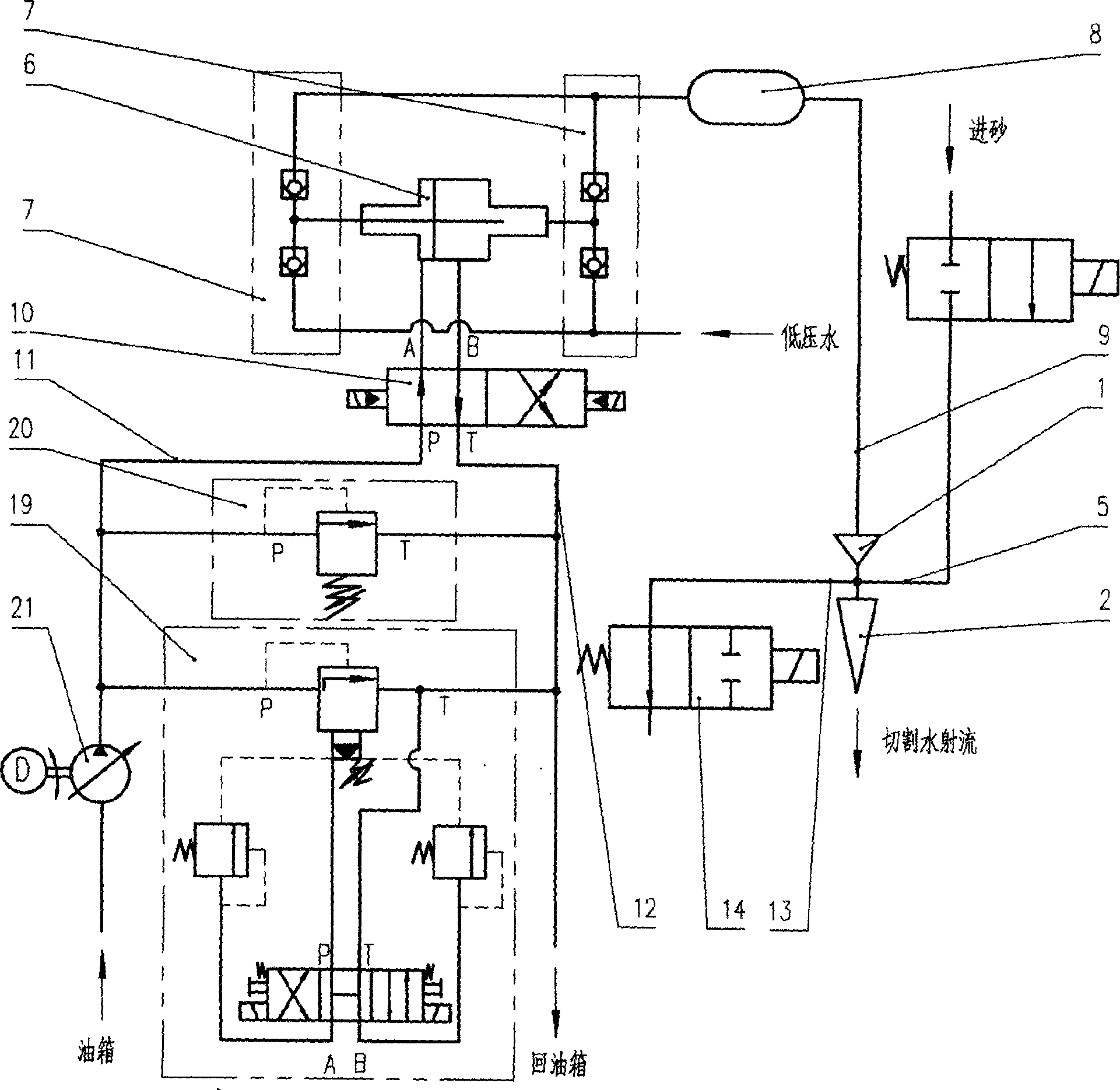
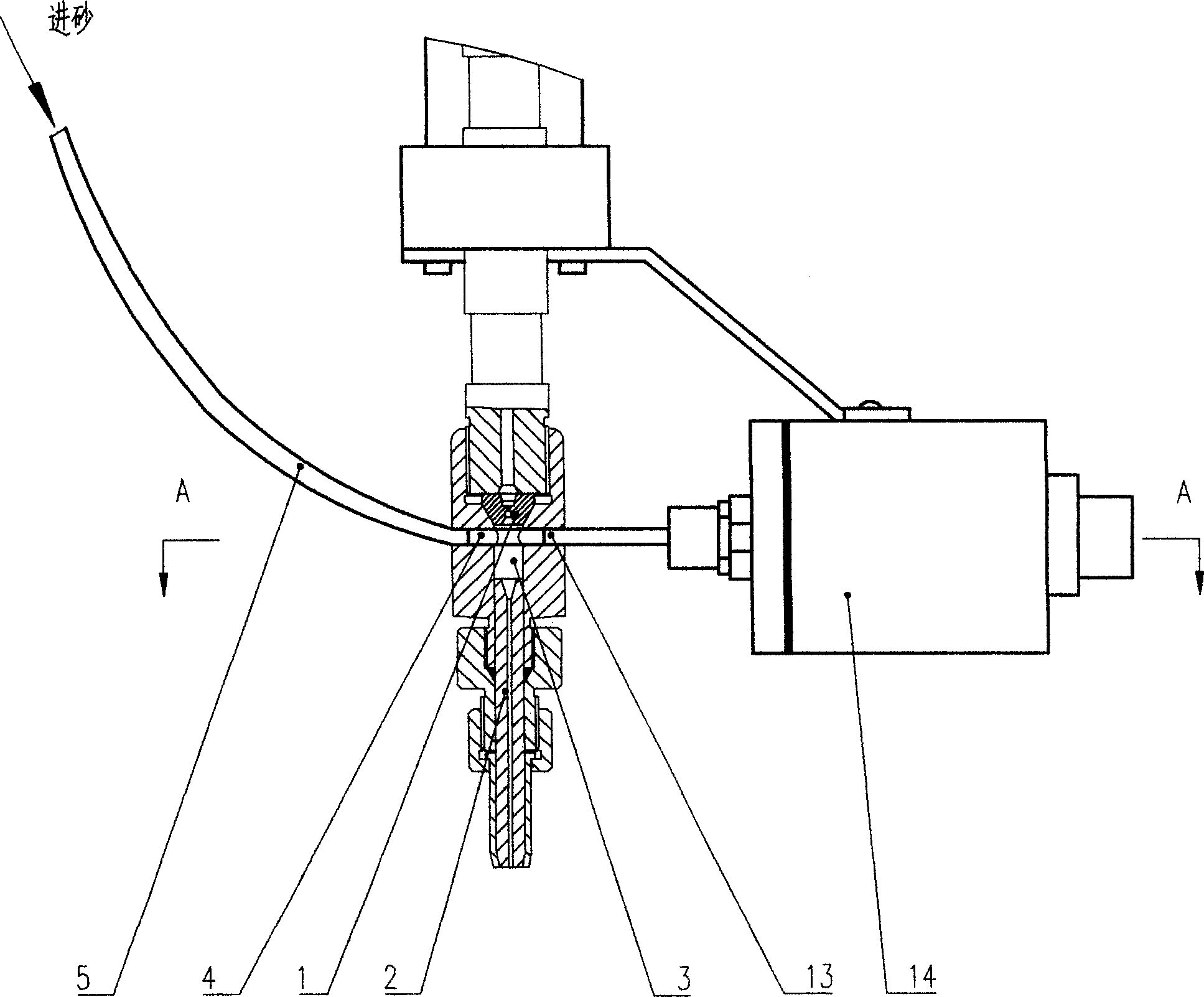
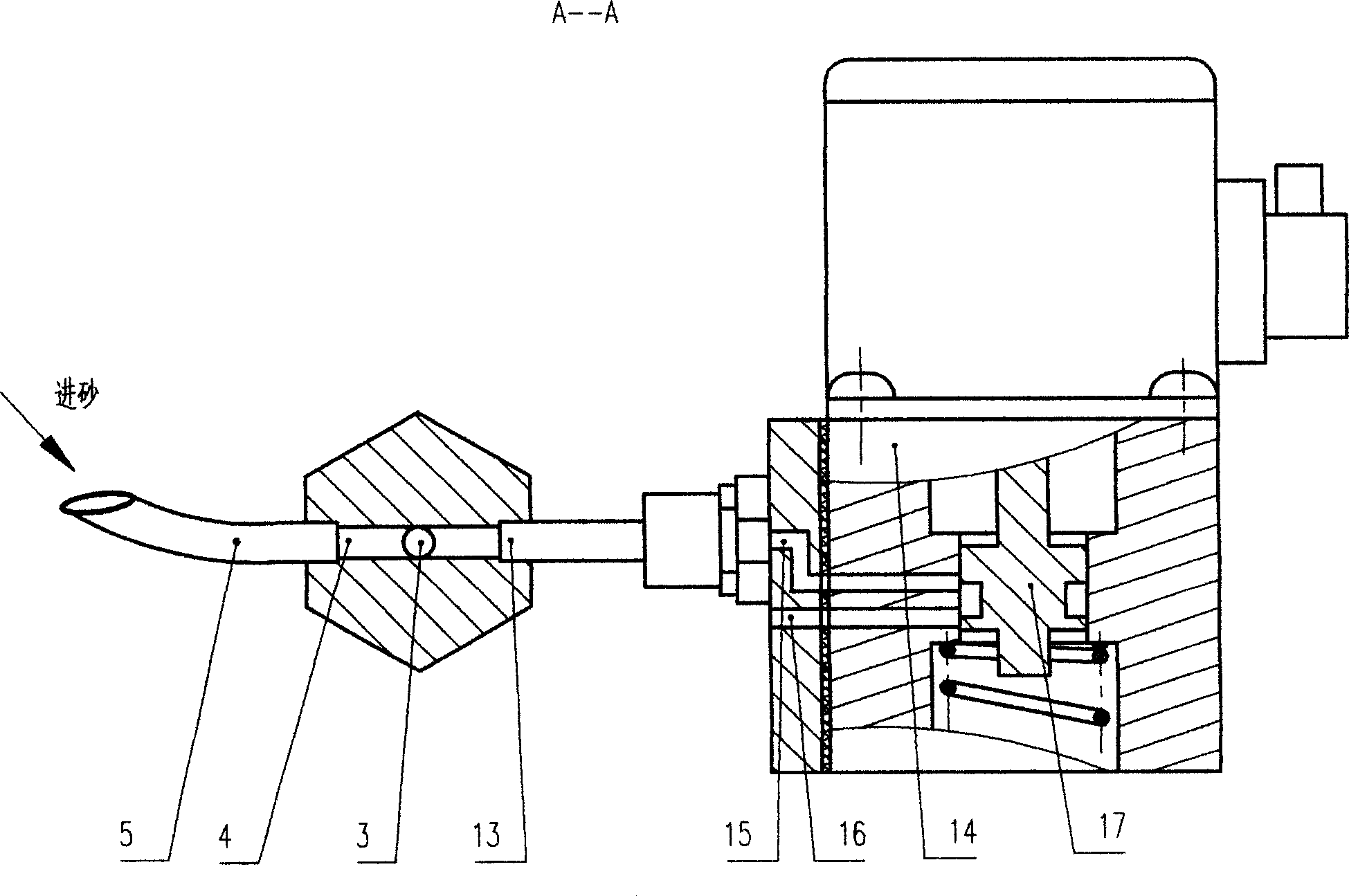
[0011] see also figure 1 , figure 2 and image 3 , the return water control system of the water cutting machine includes a water nozzle 1 and a sand nozzle 2 connected in series along the water flow direction, and a sand inlet 4 is opened in the mixing chamber 3 between the water nozzle 1 and the sand nozzle 2, and the sand inlet 4 is connected to Sand delivery pipe 5 is arranged. The water inlet of the water nozzle 1 is connected to an ultra-high pressure water generation system, which includes a supercharger 6, and the high-pressure water output port of the supercharger 6 is connected to a high-pressure water accumulator 8 through a combined check valve 7, and the high-pressure The water accumulator 8 is connected to the water nozzle 1 through the water delivery pipe 9, the two oil inlet and outlet ports of the supercharger cylinder are respectively connected to the execution output port of the reversing valve 10, and the high-pressure oil input port and the oil return po...


PUM


Abstract

A backwater control system of hydraulic cutting machine is composed of water nozzle, sand nozzle, mixing cavity between the said two nozzles and connected to sand delivering pipe, and a high-pressure water generator system having a boosting unit and a high-pressure water accumulator connected to the said water nozzle. It features that a by-pass channel communicated with the said mixing cavity is used for discharging the backwater via a normally opened valve. Its advantages are simple structure and low cost.

Description

technical field [0001] The invention relates to the structure of the water cutting machine, in particular to the water return control system of the water cutting machine. Background technique [0002] The water cutting machine has a water nozzle and a sand nozzle connected in series along the direction of water flow, a sand inlet is opened in the mixing chamber between the water nozzle and the sand nozzle, the sand inlet is connected to a sand delivery pipe, and the water nozzle inlet is connected to a super High-pressure water generation system connection, the system includes a supercharger, the high-pressure water output port of the supercharger is connected to the high-pressure water accumulator through a combined check valve, and the high-pressure water accumulator is connected to the water nozzle through a water delivery pipe, increasing The two oil inlets and outlets of the pressurizer cylinder are respectively connected to the executive output port of the reversing va...

Claims


Application Information

Patent Timeline
IPC IPC(8): B24C9/00
Inventor 郑振忠钟龙辉
Owner KEDA INDUSTRIAL GROUP CO LTD
Why Eureka
Try Eureka