
Process and device for making air metal intlet of fan

A processing technology and air inlet technology, applied in the field of fan metal air inlet processing technology and its equipment, can solve the problems of cumbersome procedures, poor quality of parts, etc., and achieve the effects of improving work efficiency, convenient operation and saving raw materials

Inactive Publication Date: 2003-05-28
山东新风股份有限公司
View PDF0 Cites 8 Cited by
  • Summary
  • Abstract
  • Description
  • Claims
  • Application Information

AI Technical Summary

Problems solved by technology

This method is easier to form each part, but the disadvantage is that the quality of the parts is poor and the process is cumbersome.

Method used


Image

  • Process and device for making air metal intlet of fan
  • Process and device for making air metal intlet of fan
  • Process and device for making air metal intlet of fan

Examples


Embodiment Construction

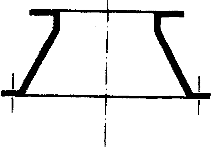
[0027] Such as Figure 6 , which is the shape structure of the metal air inlet of the fan.

[0028] The processing technology is:

[0029] 1. Unloading, according to the size of the air inlet, a circular material plate is unloaded;

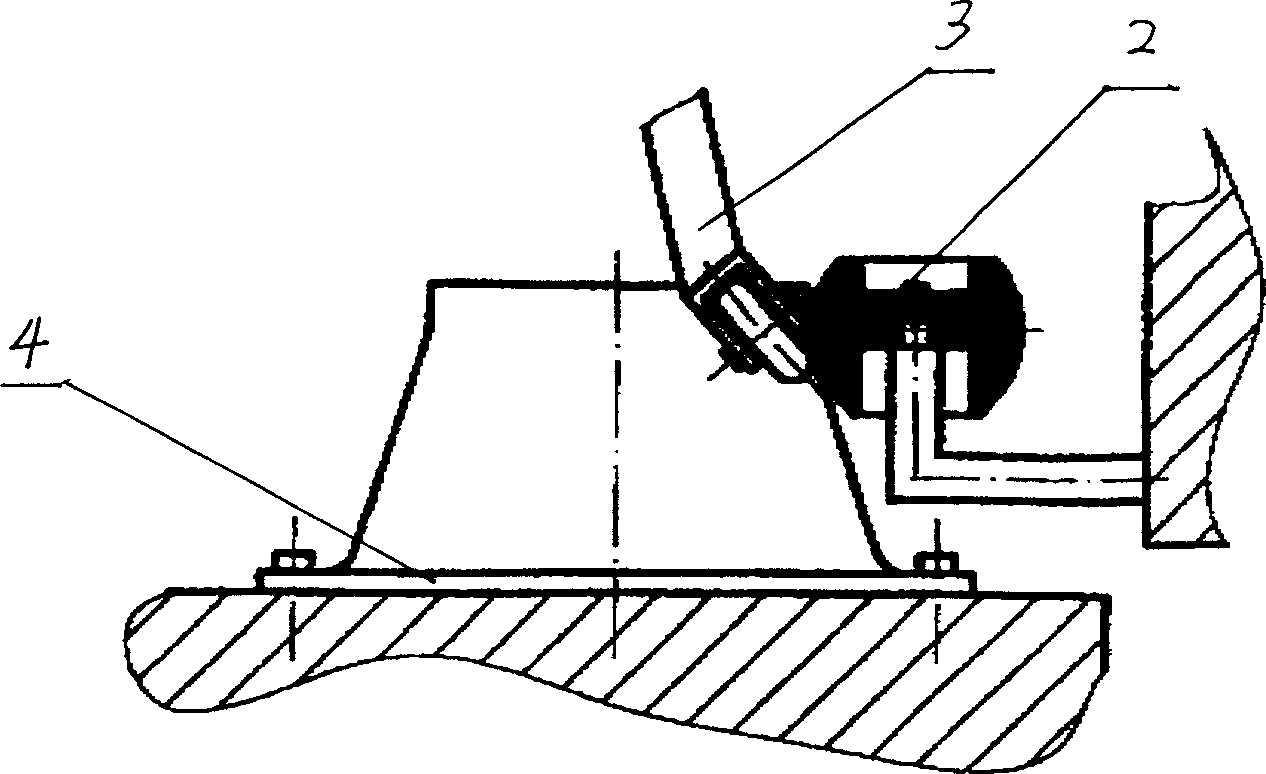
[0030] 2. Fix the material plate on the bottom surface of the fixed mold, drive the fixed mold and the material plate to rotate on the fixed mold fixing lathe, and use the spinning wheel 3 to spin the material plate into a cone-shaped workpiece;

[0031] 3. Unload the cone-shaped workpiece from the fixed mold, install it on the bottom plate 4, and anneal the cylindrical part of the upper mouth;

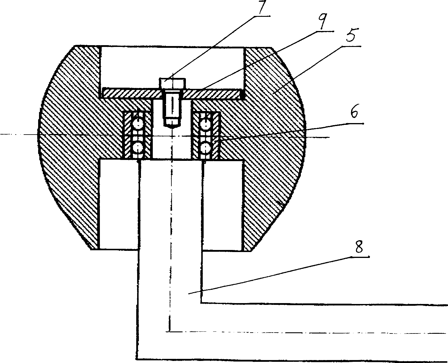
[0032] 4. If image 3 , put the cylindrical part of the cone-shaped upper mouth against the movable mold 2, and also use the spinning wheel 3 to flang the part;

[0033] 5. After the flanging is completed, the edge trimming is carried out, the movable mold leaves the workpiece, and the unloaded workpiece is the air inlet.

[0034] The shape of the fix...


PUM


Abstract

A technique for manufacturing the metallic intake opening of blower includes such steps as blanking metallic plate, die pressing to obtain conic workpiece, annealing the top opening, flanging and edging. Its advantages are no welded seam, high surface quality, low cost and high productivity.

Description

technical field [0001] The invention relates to a processing technology and equipment for a fan metal air inlet. Background technique [0002] Fan metal air inlet, such as Figure 6 As shown, it is roughly in the shape of a cone, and the upper mouth of the cone is in the form of a flanging. Assuming that the material thickness is t, when t / B≤0.003, H / B≥0.38, and A / B≥0.65, the forming process becomes quite complicated. Most domestic fan manufacturers use welding forming process. There are two methods: method One: blanking; welding cone shape; pressing arc Ra; pressing arc Rb. It is often difficult to determine the expansion size of this method, and it can only be based on experience. It is easy to wrinkle when pressing arc Ra, and easy to break when Rb is pressed. The required tooling is Ra and Rb compression molds, which must be completed on a hydraulic press with a relatively large work surface. Method 2: Divide the air inlet into three par...

Claims


Application Information

Patent Timeline
Patent Type & Authority Applications(China)
IPC IPC(8): B21D19/00B21D22/16
Inventor 李福良
Owner 山东新风股份有限公司
Learn More