Server load sharing system

A load sharing and server technology, applied in transmission systems, digital transmission systems, instruments, etc., can solve problems such as server load balancer processing speed bottlenecks

Inactive Publication Date: 2003-06-25
FUJITSU LTD
View PDF0 Cites 21 Cited by
  • Summary
  • Abstract
  • Description
  • Claims
  • Application Information

AI Technical Summary

Problems solved by technology

If, according to the protocol, there is a concentration of packet traffic forwarded in the communication between the server and the client, it is still inevitable that the corresponding server load balancer becomes the bottleneck of the processing rate

Method used


Image

  • Server load sharing system
  • Server load sharing system
  • Server load sharing system

Examples


Embodiment Construction

[0051] Embodiments of the present invention will be described below in conjunction with the accompanying drawings.

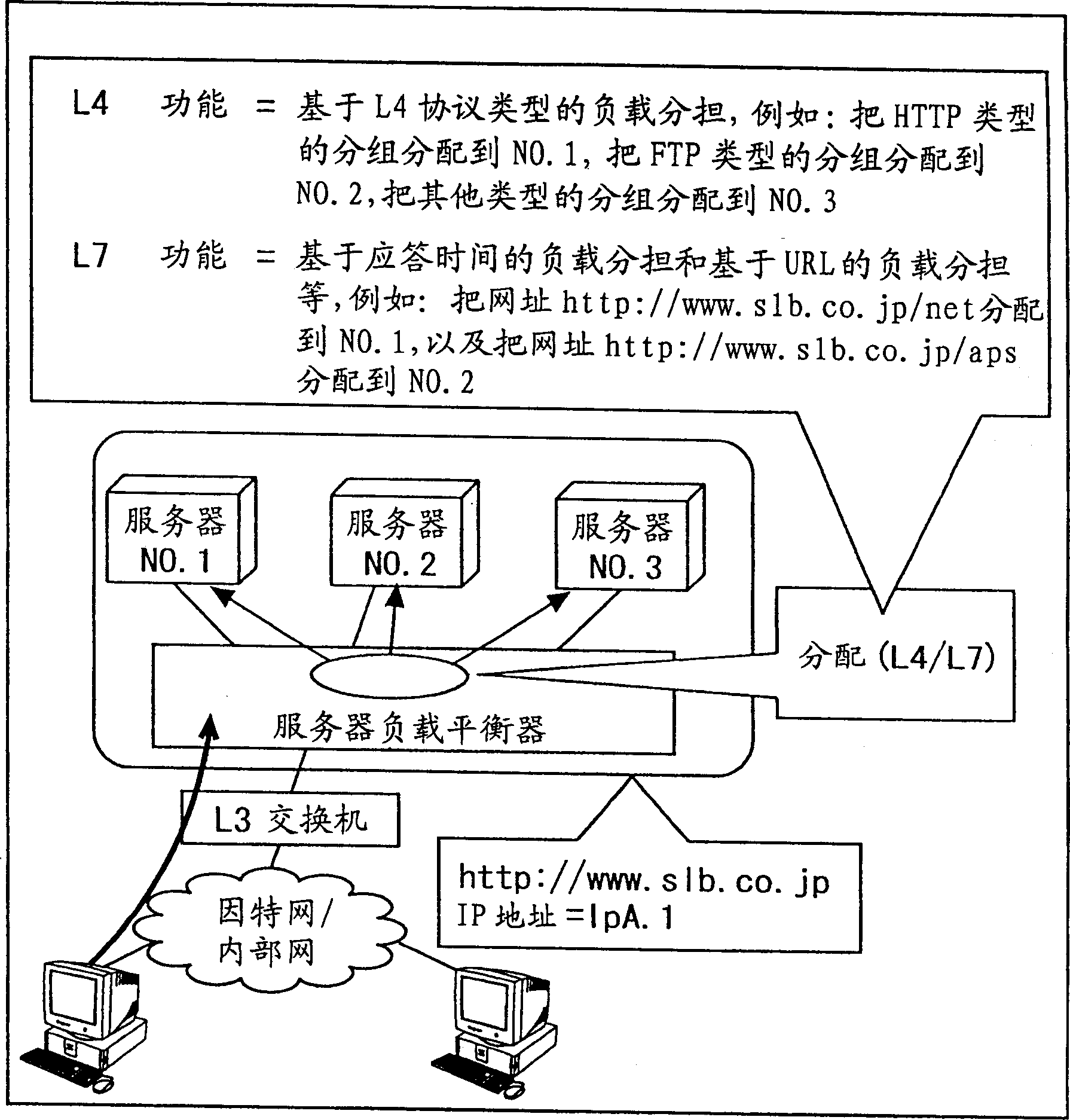
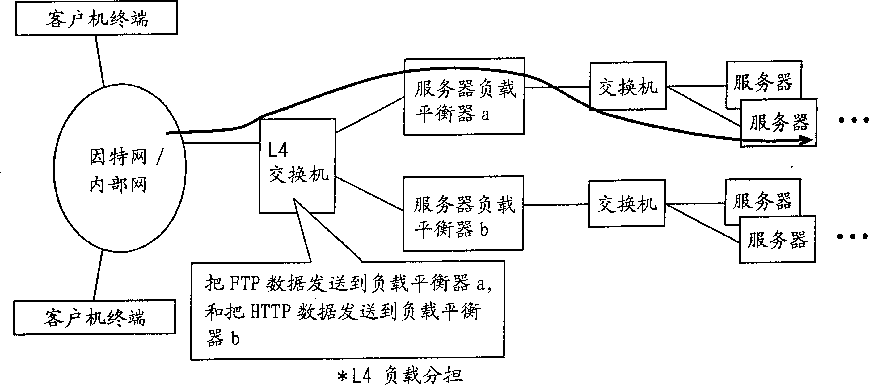
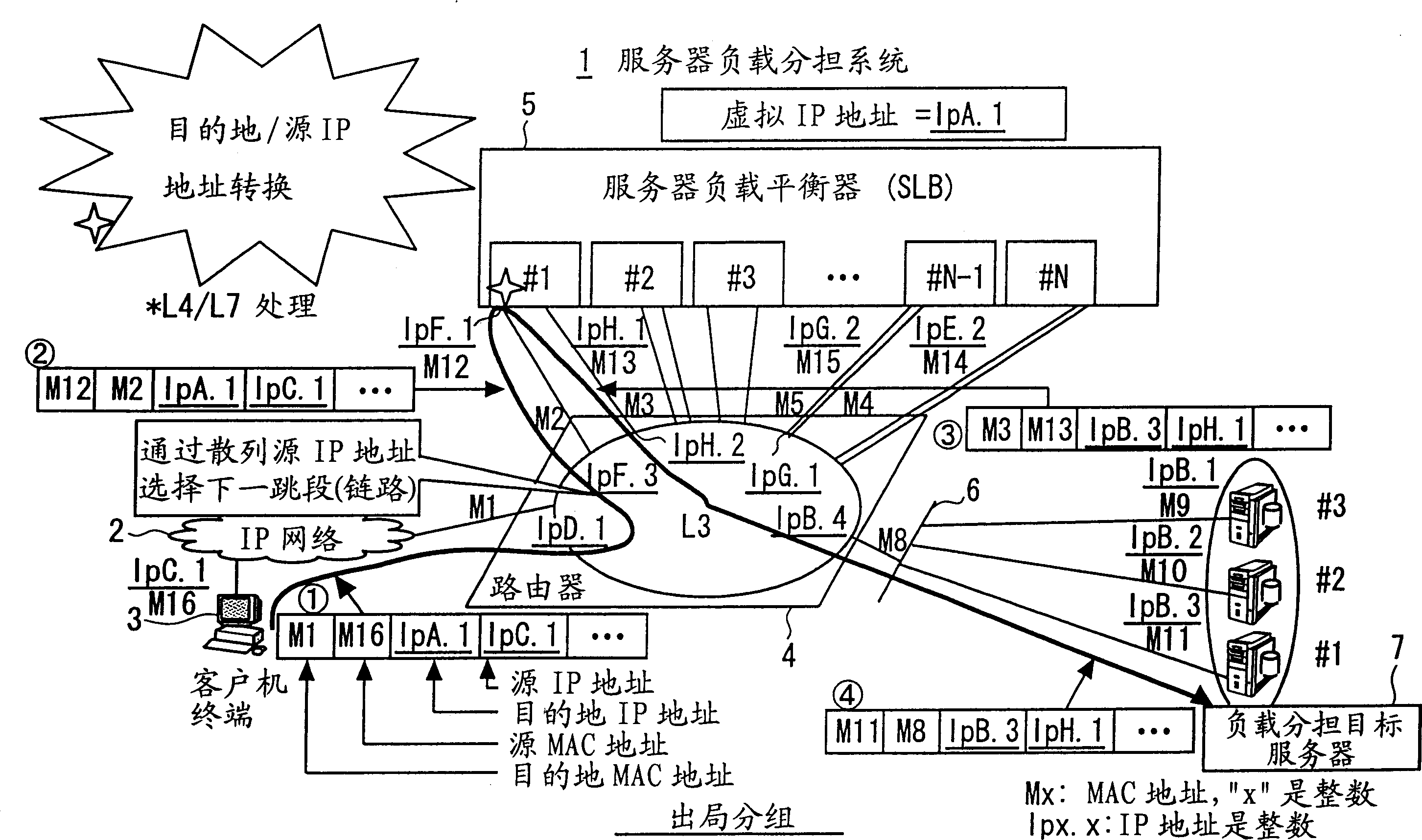
[0052] [Structure of Server Load Sharing System]

[0053] image 3 and 4 It shows the structure of a server load sharing system in an embodiment of the present invention, and shows an outgoing flow and a return flow of packets respectively.

[0054] refer to image 3 and 4 , the server load sharing system 1 includes: a plurality of client terminals 3 (one of which is described as a typical terminal) such as personal computers connected to an IP network 2 (such as the Internet or an intranet); connected to the IP network 2 a router 4; a plurality of server load balancers (SLB#1, #2 to #N) 5 connected to the router 4; and a server group defined as a load sharing target server connected to the router 4 through a LAN (Local Area Network) 6 Multiple servers (#1, #2, #3)7.

[0055] The router 4 as a network relay device may be replaced by an L3 switch that inter...


PUM


Abstract

A server load sharing system having a plurality of server load balancers and a relay device. Each balancer includes a module selecting, any one of a plurality of load sharing target servers specified in their group on the basis of the virtual IP address and each allocated a unique IP address, and a module rewriting a virtual IP address of the received forwarding target packet addressed to the virtual IP address into the unique IP address of the selected server, and rewriting a source IP address of the received packet addressed to the virtual IP address into an IP address capable of specifying the other of the first and second links.

Description

technical field [0001] The present invention relates to a server load sharing system in which communication between servers and clients is performed in a manner to maintain server load sharing through an IP (Internet Protocol) network such as the Internet or an intranet. Background technique [0002] Through multi-link PPP (point-to-point protocol) and multi-cost equal path (multi-cost equal path), a conventional load sharing method is exemplified. [0003] Multilink PPP is defined as a method used in ISDN (Integrated Services Digital Network), etc., and is designed to provide multiple links (physical lines) between adjacent systems if the line rate is low, and Distribute the load to these links. For example, by using 2B channels (64Kbps) in ISDN, multilink PPP can provide communication with a bandwidth of 128Kbps (transmission rate). [0004] Furthermore, the multi-cost equal path is defined as a method of reserving multiple paths to minimize the cost to a destination in ...

Claims


Application Information

Patent Timeline
Patent Type & Authority Applications(China)
IPC IPC(8): G06F15/177G06F9/50G06F13/00H04L45/02H04L45/24
CPCH04L67/1008H04L67/1019H04L29/12377H04L29/12839H04L67/1017H04L61/6022H04L67/1023H04L67/1002H04L61/2517H04L2101/622H04L67/1001
Inventor 井上留美子武田浩一
Owner FUJITSU LTD
Why Eureka
Try Eureka