Eureka AIR delivers breakthrough ideas for toughest innovation challenges, trusted by R&D personnel around the world.

Polar armature

A technology of pole electricity and current, applied in the field of pole armature, can solve the problems of large footprint and insufficient cooling efficiency

Inactive Publication Date: 2003-07-02
SIEMENS AG
View PDF1 Cites 12 Cited by
  • Summary
  • Abstract
  • Description
  • Claims
  • Application Information

AI Technical Summary

Problems solved by technology

However, the disadvantage of the above-mentioned pole armature is that its cooling efficiency is insufficient
Therefore, poles of different phases of a circuit breaker can only be mounted at a considerable distance from one another, resulting in a large footprint of switchboards, especially in medium-voltage switchgear

Method used


Image

  • Polar armature
  • Polar armature
  • Polar armature

Examples


Embodiment Construction

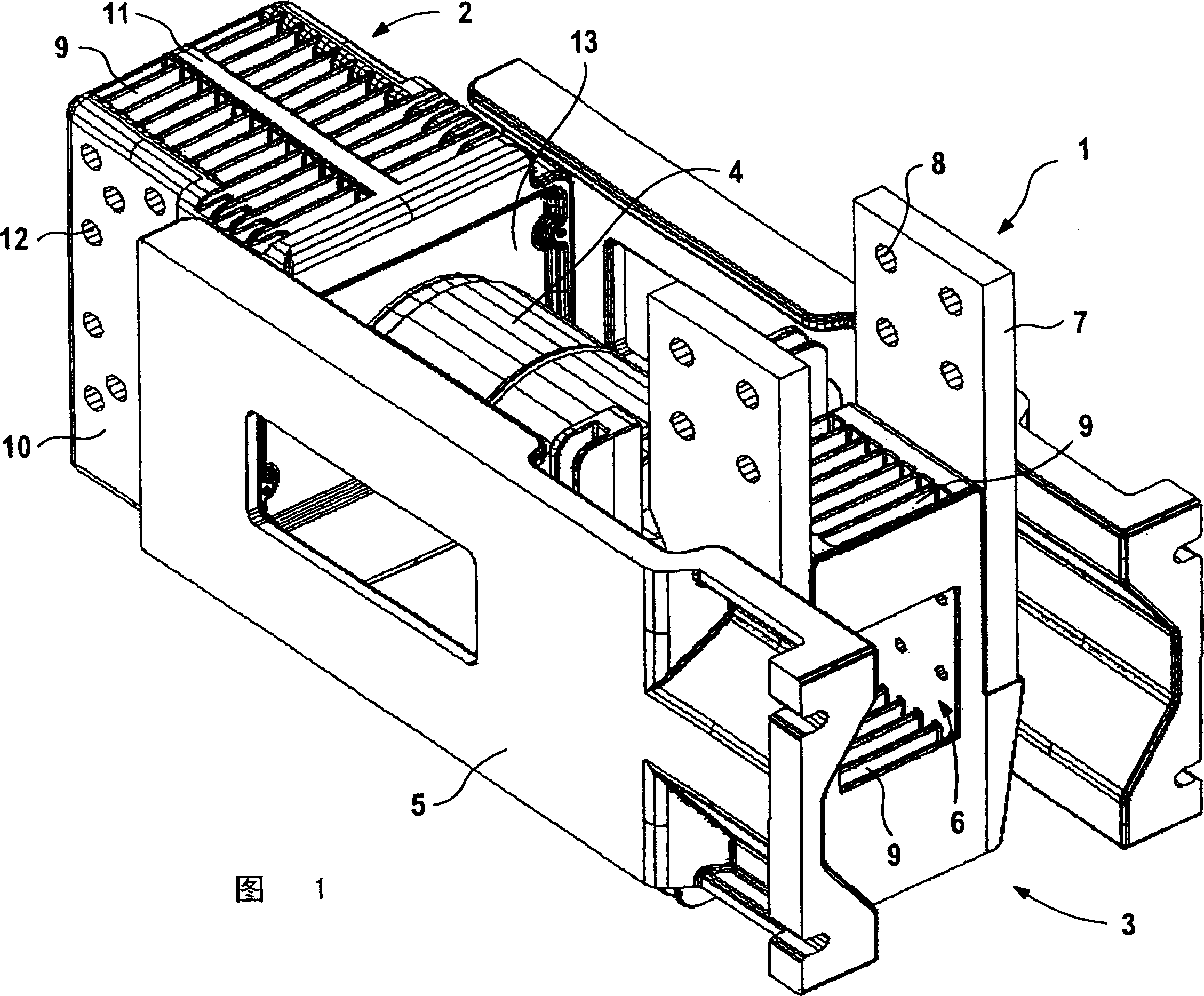
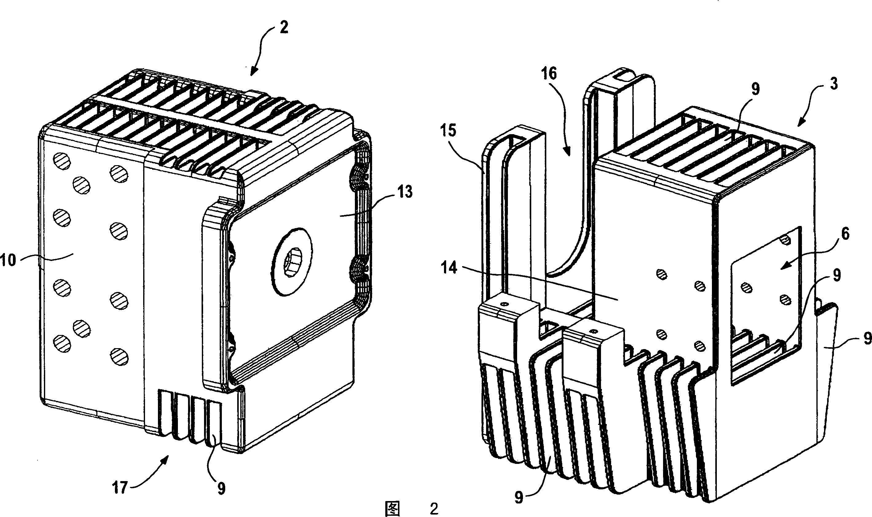
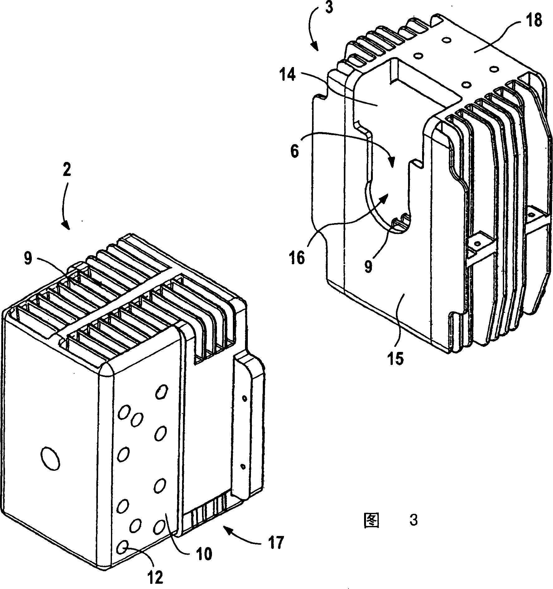
[0030] FIG. 1 shows a switching pole of a circuit breaker 1 with an embodiment of a pole armature according to the invention, which consists of a pole head 2 and a pole carrier 3 . Arranged between the pole head 2 and the pole carrier 3 is an arc quenching unit 4 which, in the exemplary embodiment shown, is a vacuum switch. For the mechanical connection and support of the pole armature, a pole shell 5 made of non-conductive insulating material is provided, which extends to both sides of the vacuum switch 4 and connects to the pole head 2 and the pole head 2 at the connection point provided for this purpose. Connect with pole support 3.

[0031] The pole support 3 has an orifice 6 through which the operating rod or other parts of the operating mechanism can pass in the direction of the vacuum switch 4 in order to push the moving contact of the vacuum switch 4 into the contact position or in the non-contact position Break the current.

[0032] Furthermore, two busbars 7 with h...


PUM


Abstract

The invention relates to a polar armature for surpporting and connecting an arc suppression unit 4 of a breaker 1 in a protective gas. The polar armature is composed of a pole head 2 and / or pole carrier 3, respectively with cooling fins 9 for cooling. In order to improve the cooling effect even though the structure of the breaker 1 is compact, the cooling fins 9 of the pole head 2 and / or pole carrier 3 are separated by 6-13 mm. Their length is 150-250 mm in the gas flow direction. Furthermore, the pole head 2 and / or pole carrier 3 can comprising an exterior delimitation pole 10, the cooling fins 9 arranged inside the pole head 2 and / or pole carrier 3. Another possibility is that the pole head 2 and / or pole carrier 3 form cube along envelope curve thereof.

Description

technical field [0001] The invention relates to a pole armature for supporting and connecting an arc extinguishing unit of a circuit breaker in a gas, especially in a protective gas, the pole armature consists of a pole head and a pole support, which Each has a heat sink for cooling. Background technique [0002] Contacts are known to heat up when current flows through them. Especially in medium voltage technology, the heat generated in the interrupter unit due to the high current limits the use of circuit breakers. Therefore, it is necessary to specify, for example, a maximum temperature that must not be exceeded. When this maximum temperature is exceeded, for example, due to melting or oxidation of other components, it will cause damage to the equipment installed with the circuit breaker and cannot be repaired. For this reason, it is best to use cooling elements to reduce the operating temperature of high current circuit breakers. Especially for vacuum circuit breakers....

Claims


Application Information

Patent Timeline
IPC IPC(8): H01H9/52H01H33/02H01H33/66
CPCH01H33/6661H01H2033/6613H01H33/025H01H33/6606H01H9/52H01H2033/6665
Inventor W・切赫T・雷赫尔H・舍恩塔格R・韦伯
Owner SIEMENS AG
Why Eureka
Eureka Blog
Learn More