Accumulator

A technology for batteries and battery containers, which is applied to dry batteries, secondary batteries, primary batteries, etc., can solve the problems that the separator cannot fully retain the electrolyte, the battery characteristics of power generation elements are uneven, and the electrolyte is difficult to penetrate.

Inactive Publication Date: 2003-07-02
GS YUASA INT LTD
View PDF0 Cites 10 Cited by
  • Summary
  • Abstract
  • Description
  • Claims
  • Application Information

AI Technical Summary

Problems solved by technology

[0017] Therefore, it is difficult for the electrolyte to infiltrate in the area of ​​the arc portion S, especially when the separator is excessively squeezed and the porosity decreases, causing the electrolyte to be insufficiently retained in the separator and affecting the charge and discharge characteristics of the battery. Causes adverse effects and causes variations in characteristics between power generation elements or batteries
[0018] In addition, if the tightening force is too loose, the distance between the positive and negative electrodes will not be stable, which will cause unevenness in the characteristics of the power generation elements or between the batteries.

Method used


Image

  • Accumulator
  • Accumulator
  • Accumulator

Examples


Embodiment 1

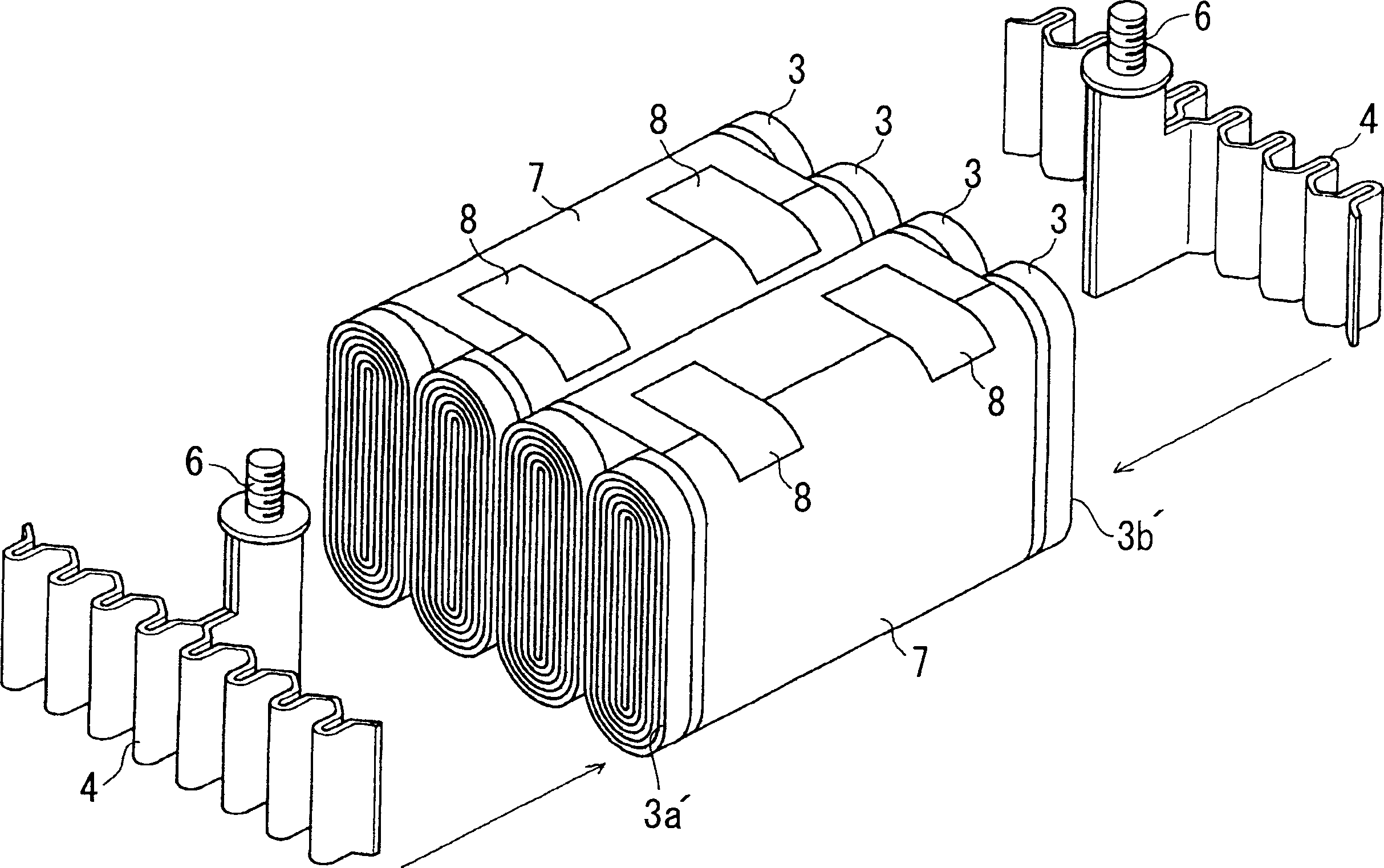
[0048] Figure 1-3 The first embodiment of the present invention is shown as a large non-aqueous electrolyte secondary battery in which four elongated cylindrical wound power generating elements 3 are placed in a battery container 1 .

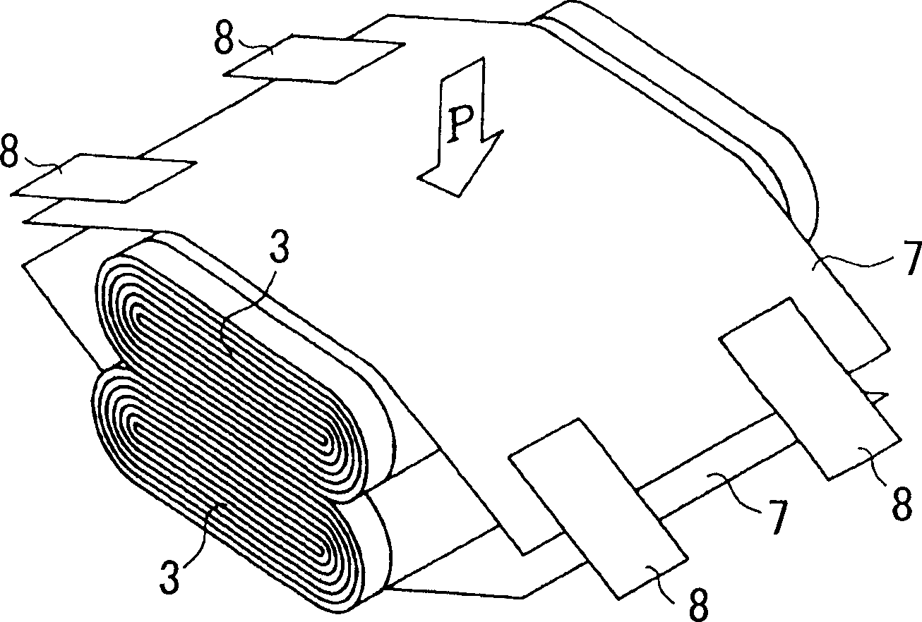
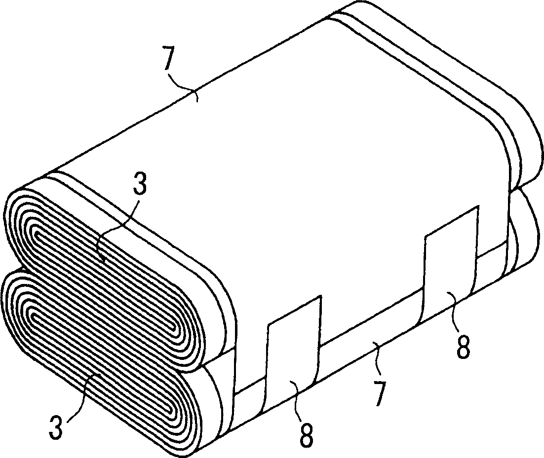
[0049] figure 1 It is a schematic perspective view showing a method of covering two power generating elements 3 up and down with two sheets 7 and binding them with adhesive tape (adhesive tape) 8 . figure 2 It is a perspective view showing two power generating elements 3 covered with a sheet 7 and fastened with an adhesive tape 8 . image 3 It is a perspective view showing a method of connecting and fixing the current collector connecting body 4 to the power generating element 3 covered with the sheet 7 and fastened with the adhesive tape 8 .

[0050] The nonaqueous electrolyte secondary battery and Figure 9 , Figure 10 In the same way as the prior art example shown, the flat parts of the peripheral side surfaces of four elongated cylind...

Embodiment 2

[0069] Next, another embodiment of the present invention will be described. This embodiment is an example of using a non-aqueous electrolyte secondary battery having a current collecting structure different from that of the above-mentioned first embodiment, and bending the metal foil of the electrode protruding from the end surface of the power generating element at the arc portion. example.

[0070] In this embodiment 2, the power generating element 3 and the collector connection structure are used such as Figure 4 and Figure 5 the form shown. This non-aqueous electrolyte secondary battery is formed by connecting two elongated cylindrical power generating elements 3, 3 side by side in parallel.

[0071] Each collector connector 4 is composed of a substantially ladder-shaped collector connector body 4a arranged horizontally and four elongated electrode connection parts 4b branching downward from the bottom of the body 4a. In addition, a plurality of protrusions protrudin...


PUM

PropertyMeasurementUnit
thicknessaaaaaaaaaa
widthaaaaaaaaaa

Abstract

A cell such as a nonaqueous electrolytic secondary cell includes a plurality of power-generating elements which each include a strip-like positive electrode and a strip-like negative electrode that are both wound into an elliptic cylinder with a separator being interposed therebetween, where each power-generating element has a peripheral face including at least a flat portion. The cell also includes a cell case for housing the power-generating elements, where the cell case has an opening, and a cover hermetically sealing the opening of the cell case. The flat portion of each power-generating element is superposed on the flat portion of the adjacent power-generating element, and a sheet member is wound around peripheries of the superposed power-generating elements to fasten the power-generating elements such that the power-generating elements are integrated.

Description

technical field [0001] The present invention relates to a battery having an elongated cylindrical wound power generating element, particularly a battery having a plurality of elongated cylindrical wound power generating elements. Background technique [0002] Among bulk batteries having a large discharge capacity, there is a type in which a plurality of elongated cylindrical winding-type power generating elements are stacked and used in a battery container. For example, in such a nonaqueous electrolyte secondary battery, such as Figure 9 As shown, the flat parts of the peripheral side surfaces of four elongated cylindrical winding-type power generating elements 3 are superimposed on each other and loaded into the battery container 1 . [0003] The connection structure of the power generating element 3 and the collector connector 4 of this non-aqueous electrolyte secondary battery is as follows: Figure 10 shown. The non-aqueous electrolyte secondary battery is composed of...

Claims


Application Information

Patent Timeline
Patent Type & Authority Applications(China)
IPC IPC(8): H01M4/64H01M6/00H01M6/10H01M6/42H01M10/04H01M10/38H01M50/147
CPCH01M10/04H01M2/16H01M2/04H01M10/0413H01M2/145H01M2/263H01M6/42H01M10/0463Y02E60/10H01M50/147Y02P70/50
Inventor 胸永训良下薗武司田才博志铃木勲
Owner GS YUASA INT LTD
Why Eureka
Try Eureka