Feed horn structure and its manufacturing method, frequency transformer and satellite communication receiving antenna
A feeding horn and satellite communication technology, which is applied in the field of satellite communication receiving antennas, can solve problems such as cost increase, coordination force damage, and fracture
- Summary
- Abstract
- Description
- Claims
- Application Information
AI Technical Summary
Problems solved by technology
Method used
Image
Examples
no. 1 example
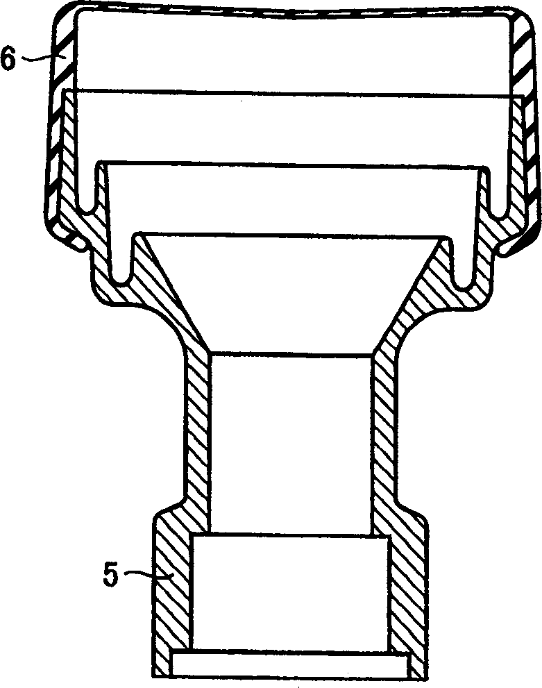
[0044] figure 1 is a front view showing a vertical section of the feed horn structure according to the first embodiment of the present invention. The horn cap 6 and the die-cast feed horn 5 are integrated together by integral molding. Therefore, it is not necessary to use a buckle to mount the horn cap to the feed horn in the manufacturing step, so that whitening, breakage, etc. do not occur. Accordingly, manufactured products are improved, and manufacturing costs are reduced. Also, an expensive O-ring for maintaining airtightness can be eliminated, so cost reduction can be achieved.
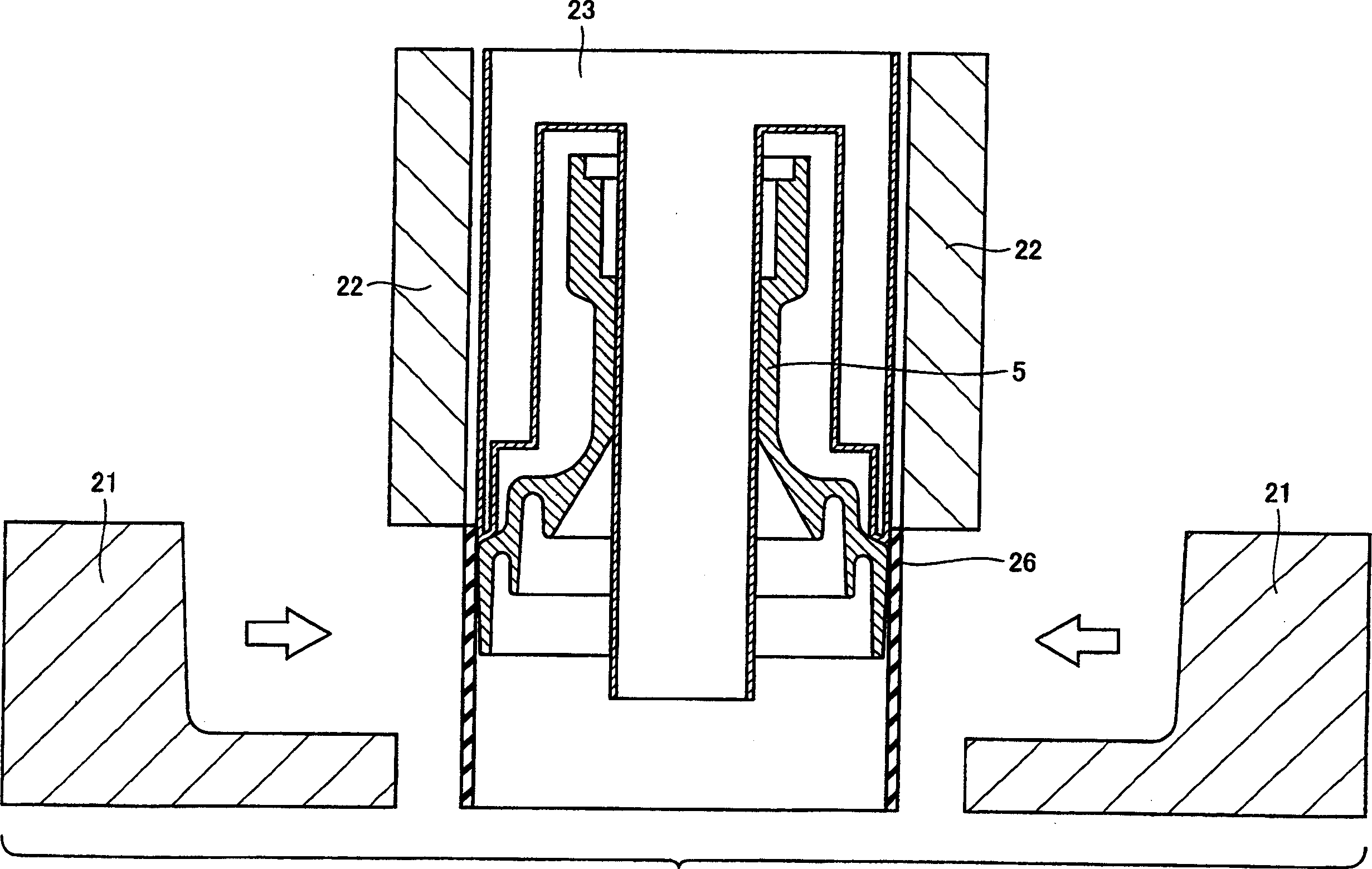
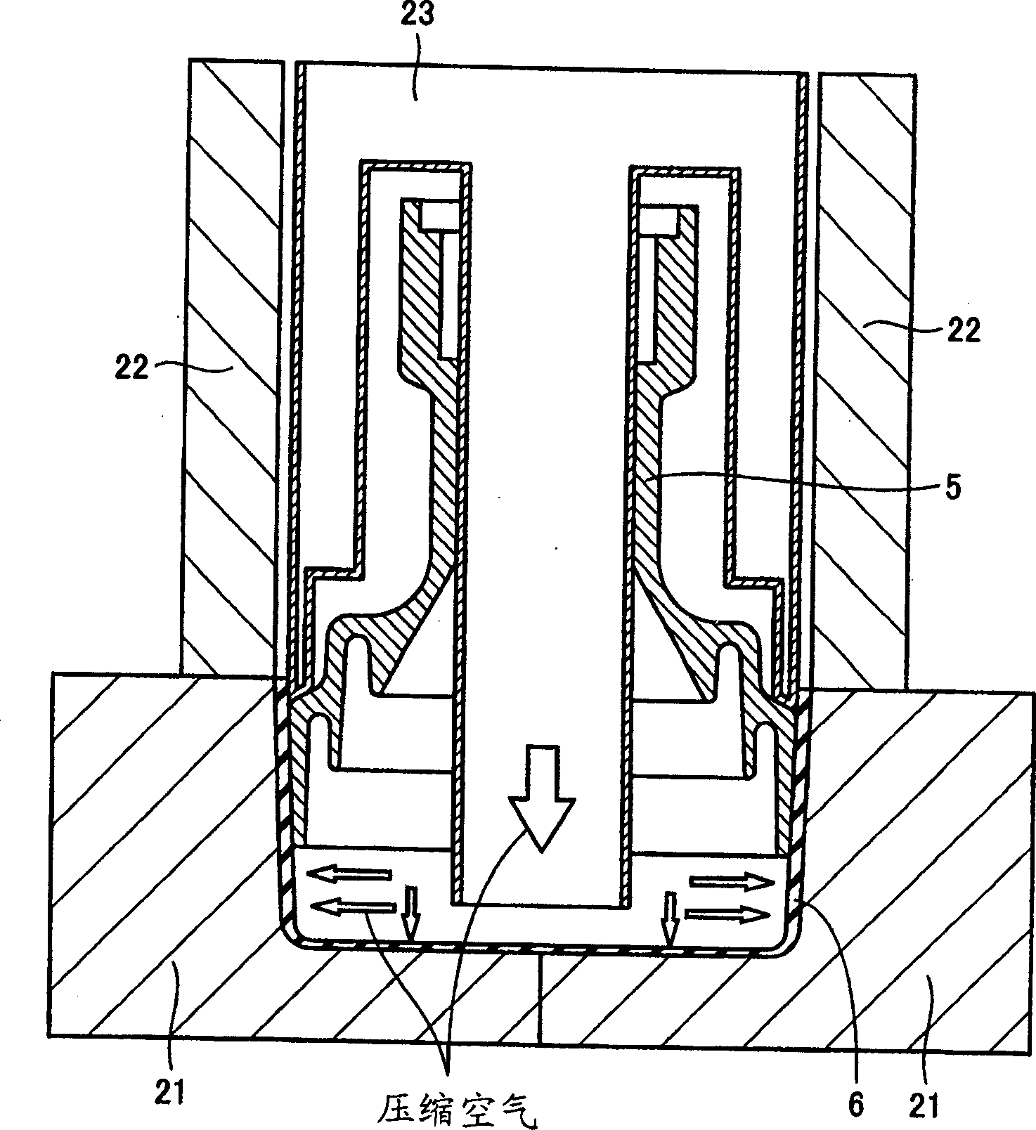
[0045] Next, will describe figure 1 The fabrication method of the feed horn structure shown. First, if figure 2 Feed horn 5 is mounted to blow molds 22 and 23 as shown. Then, the molded parison 26 of resin material is fitted to a port of the feed horn, and is compressed with the blow mold 21 . Thereafter, if image 3 As shown, compressed air is blown in so that the horn cap 6 is shape...
no. 2 example
[0047] Figure 4 is a front view showing a vertical cross-section of the feed horn structure according to the second embodiment of the present invention. Figure 5 According to the feed horn structure of the second embodiment of the present invention, along Figure 4 A horizontal cross-sectional view of the V-V line. In the above feed horn structure, in order to prevent the rotational displacement of the horn cap 6 relative to the feed horn 5, a protruding portion 7 is provided on the feed horn 5, and a concave portion is provided on the horn cap 6, so that Compatible with protrusions.
[0048] Figure 6 is a front view showing a vertical cross-section of the feed horn structure according to a modification of the second embodiment of the present invention. Figure 7 According to the feed horn structure of the modification of the second embodiment of the present invention, along Figure 6 Horizontal section view of line VII-VII. In this feed horn structure, with Figure ...
no. 3 example
[0051] Figure 8 is a front view showing a vertical section of a structure of a feed horn according to a third embodiment of the present invention. The feed horn structure of the third embodiment is characterized in that it includes a feed horn 5 formed by molding a feed horn shape with a waterproof resin 9 and providing a plating layer 10 on its inner surface. With the above feed horn, the structure of the feed horn can be integrated, and its weight can also be reduced.
[0052] Figure 9 is a front view showing a vertical cross-section of the feed horn structure according to a modification of the third embodiment of the present invention. In a modification of the third embodiment, the feed horn 5 is formed by forming a feed horn shape with a general-purpose resin and covering its entirety with a plating layer 12 . The horn cap 13 is formed to cover the periphery of the feed horn. pass Figure 9 The variant shown, can provide a comparison to Figure 8 The feed horn stru...
PUM
 Abstract
Description
Claims
Application Information
 - R&D
- Intellectual Property
- Life Sciences
- Materials
- Tech Scout
- Unparalleled Data Quality
- Higher Quality Content
- 60% Fewer Hallucinations
Browse by: Latest US Patents, China's latest patents, Technical Efficacy Thesaurus, Application Domain, Technology Topic, Popular Technical Reports.
© 2025 PatSnap. All rights reserved.Legal|Privacy policy|Modern Slavery Act Transparency Statement|Sitemap|About US| Contact US: help@patsnap.com


