
Power distibution circuit fault location and isolation method and device

A distribution line and fault location technology, applied to fault locations, emergency protection circuit devices, electrical components, etc., can solve problems such as isolation, large economic losses, and difficulty in fault finding and troubleshooting

Inactive Publication Date: 2003-07-16
BEIJING DONGFANG RUITONG AUTOMATION TECH
View PDF0 Cites 26 Cited by
  • Summary
  • Abstract
  • Description
  • Claims
  • Application Information

AI Technical Summary

Problems solved by technology

With the development of the urban power grid and the continuous expansion of the distribution network scale, the faults of the distribution network occur frequently, the distribution network extends to every corner, the network is dense, and there are many branches, which makes it difficult to find and eliminate faults, and the resulting economic Huge loss
At present, researchers in our country have also carried out some research on the fault location method of distribution lines, such as "method for locating distribution network faults" (application number: 99124621), "a distribution network fault detection method and detection system "(Application No.: 95117577) and so on, these technologies have proposed the location method of the distribution network fault, but these methods only locate the fault, but do not isolate the line fault area as small as possible, so that the fault caused by the fault The economic loss is still relatively large

Method used


Image

  • Power distibution circuit fault location and isolation method and device
  • Power distibution circuit fault location and isolation method and device
  • Power distibution circuit fault location and isolation method and device

Examples


Embodiment 1

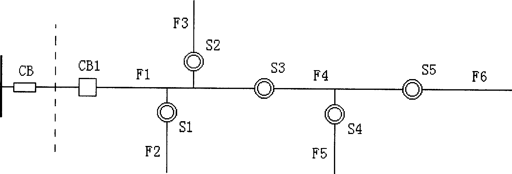
[0044] like figure 1 As shown in the figure, the outlet end of the line is equipped with the reclosing switch CB1 on the column, which is more sensitive than the reclosing switch CB in the station. When a fault occurs on the line, CB1 performs the reclosing operation for fault judgment. The main line of the line is divided into 3 sections by the subsection controlled switches S3 and S5 on the column, and the section numbers are F1, F4, F6 respectively. The three branch lines of the line are divided by the subsection controlled switches S1, S2, S4 Segmentation is performed, and the segment numbers are F2, F3, and F5. The sectional controlled switches S1, S2, S3, S4 and S5 on the column are respectively equipped with the devices R1, R2, R3, R4 and R5 of the present invention, wherein S1, S2 and S3 are connected to a node of a power distribution network, S4 and S5 are connected to the node of another power distribution network. Since the controlled switch connected to one node w...

Embodiment 2

[0054] like figure 2 As shown, the outgoing ends of the two feeders 211 and 237 are respectively equipped with on-column reclosing switches CB1 and CB2, which respectively perform reclosing operations for fault judgment. They are more sensitive than the reclosing switch in the station. When there is a fault on the line, CB1 and CB2 will perform the reclosing operation to judge the fault. The main line of the 211 feeder is divided into 3 sections by the subsection controlled switches S11 and S12 on the column, and the section numbers are F11, F12, and F13 respectively, and the branch line is divided by the subsection controlled switch S13. The main line of F14; 237 feeder is divided into 3 sections by the subsection controlled switches S21 and S22 on the column, and the section numbers are F21, F22 and F23 respectively; the ring network tie switches of the two feeders are controlled by the column controlled switch S0 served. The subsection-controlled switches S11, S12, S13, ...


PUM


Abstract

A method and apparatus for locating and isoalting the failure in distributing circuit is disclosed. Said apparatus is used in conjunction with vacuum switch, power supply, and failure segment indicator to form a core unit of an automatic distributing network system. The said method can quickly locate and automatically isolate the failure region for increasing reliability of power supply by distribution system.

Description

1. The technical field [0001] The invention relates to a method and device for detecting, locating and isolating power distribution line faults, belonging to power distribution equipment [0002] technical field. 2. Background technology [0003] my country's power grid basically inherits the system structure of the former Soviet Union, generally the voltage system of 66KV and below is called the distribution network. With the development of the urban power grid and the continuous expansion of the scale of the distribution network, the faults of the distribution network occur frequently, and the distribution network extends to every corner. Huge loss. At present, Chinese researchers have also carried out some research on distribution line fault location methods, such as "Methods for Locating Distribution Network Faults" (Application No.: 99124621), "A Distribution Network Fault Detection Method and Detection System" "(Application No.: 95117577), etc., these technologies h...

Claims


Application Information

Patent Timeline
IPC IPC(8): G01R31/08H02H7/26
Inventor 周燕宁王建国郑勇丁宪坤柳立利黎志强王洪波
Owner BEIJING DONGFANG RUITONG AUTOMATION TECH
Learn More