Measurement device and method for micropower short-wave FM radio set

A test method and micro-power technology, applied in electrical components, transmission monitoring, transmission systems, etc., can solve the problems of high price, occupying limited space in the factory, and being cumbersome, saving limited space, reducing labor costs, and reducing costs.

Inactive Publication Date: 2003-07-30
KEY MOUSE ELECTRONICS ENTERPRISE
View PDF0 Cites 4 Cited by
  • Summary
  • Abstract
  • Description
  • Claims
  • Application Information

AI Technical Summary

Problems solved by technology

[0002] With the vigorous development of science and technology, the general products used by people have gradually undergone major innovations, and the future trend of science and technology is heading in the direction of wireless telecommunications. However, various micro-power short-wave FM digital radio When products are manufactured, most of them will encounter the problem of mutual interference, and traditional testing methods (such as figure 1 As shown), the purpose of the test is to use the method of confinement of radio waves, that is, to concentrate the semi-finished products assembled on Station A 1 to a certain number, and then transport the semi-finished products to the isolation room 2 (Faraday cage) one by one. Test, and then send the tested semi-finished products to the production line, and exile to station B 3 to assemble the finished products, and the finished products will be tested again, so the finished products will be transported to the isolation room 2 (Faraday cage). Test one by one, and then send the tested finished product back to the production line for final packaging 4 and other steps. In this way, the tested object needs to go through four collections, handling, two departures from the production line and two entry into the isolation room 2, resulting in production The process wastes man-hours and inefficiencies, and may cause problems during the handling process; moreover, the above-mentioned isolation chamber 2 is made of a multi-layer metal plate with holes, which is based on the principle of electromagnetic shielding. Although the effect of blocking radio waves is good, it is too expensive and very bulky, and it takes up the limited space available in the factory

Method used


Image

  • Measurement device and method for micropower short-wave FM radio set
  • Measurement device and method for micropower short-wave FM radio set
  • Measurement device and method for micropower short-wave FM radio set

Examples


Embodiment 1

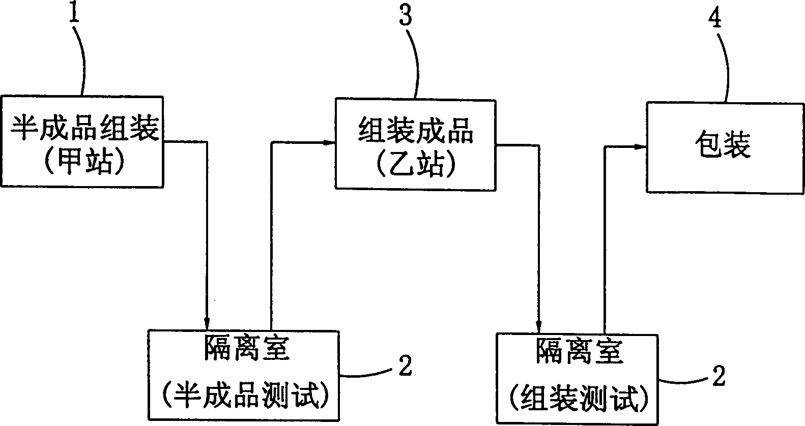
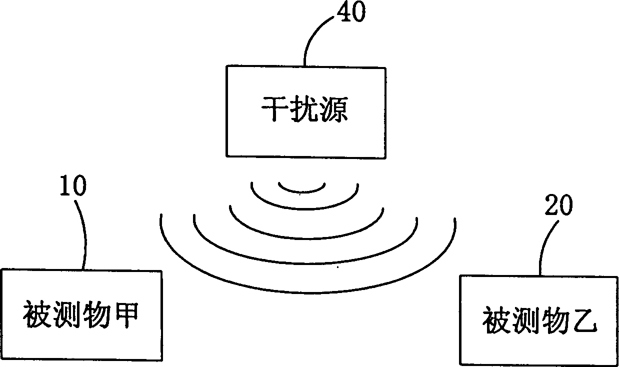
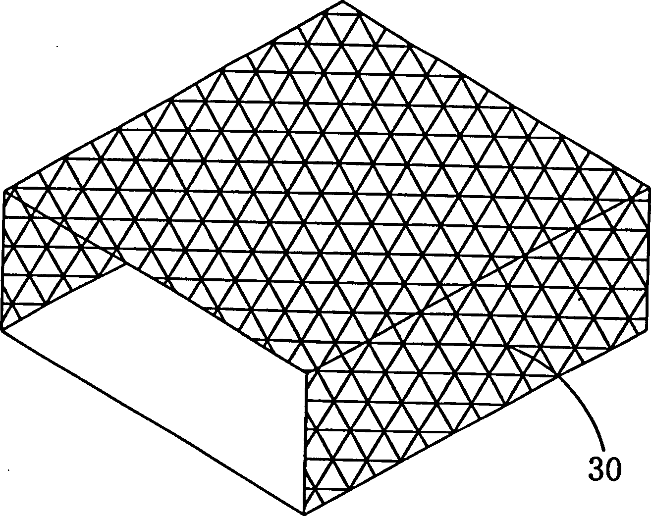
[0033] see Figure 4 . This figure is a production test flow chart of Embodiment 1 of the present invention. Such as Figure 4Shown: In the semi-finished product test station A and the finished product test station B in the production line, the transmitter and receiver of the object under test are respectively placed in an iron cage net 30 composed of barbed wire. The transmitters have the same transmission frequency , and although there is a short distance between the two stations, and the iron cage net 30 can attenuate the electric waves radiated from the inside of the cage, the effect is limited, and the two stations A and B will still interfere with each other. Another same frequency is set, but the interference transmitter of the carrier of the no-carrying signal interferes. When the two test stations are tested simultaneously, the iron cage net 30 can first attenuate the electric waves radiated to the outside, and will be disturbed by the interference transmitter. The...

Embodiment 2

[0035] Embodiment 2 is an embodiment in which an interference transmitter is respectively set between two adjacent test stations of the same station (such as Figure 5 shown), the same station described here refers to the same station with the same frequency emitted by the transmitter of the tested object in the test station; embodiment 3 is the test of two adjacent stations in more than two same stations Each of them is provided with an embodiment of a jamming transmitter (such as Figure 6 shown); Embodiments 2-3 can also fully prevent mutual interference between two adjacent test stations of the same station.


PUM


Abstract

In the present invention, set iron cage nets for containing object to be tested and its emitter and receiver at the test stations of production line and a distribance emitter with the same frequency with the emitted and carrier wave with no loaded signal is set between two iron cage nets. It is composed of frequency varying circuit, crystal osciollation and frequency regulation circuit, power regulation circuit, power output circuit and emission antenna which are connected in proper order. When they are tested, the electric wave radiated outside will be attenuated by the iron cage net and will be disturbed-damaged by the disturbance emitter, the disturbed-damaged electric wave will be again atlenuated by the iron cage net before it reaches another receiver and it will not be decoded by the receiver.

Description

technical field [0001] The present invention relates to a test device and test method of short-wave FM digital radio under micro-power, especially a kind of test station which can set up two or more anti-interference on the production line at the same time, and an interference test station is set between the two test stations. Transmitter, so as to achieve the effect of preventing mutual interference between two adjacent test stations in an all-round way. Background technique [0002] With the vigorous development of science and technology, the general products used by people have gradually undergone major innovations, and the future trend of science and technology is heading in the direction of wireless telecommunications. However, various micro-power short-wave FM digital radio When products are manufactured, most of them will encounter the problem of mutual interference, and traditional testing methods (such as figure 1 As shown), the purpose of the test is to use the me...

Claims


Application Information

Patent Timeline
Patent Type & Authority Applications(China)
IPC IPC(8): H04B17/345
Inventor 陈束学张倍铭
Owner KEY MOUSE ELECTRONICS ENTERPRISE
Why Eureka
Try Eureka