Taper threaded joint

A tapered thread and threaded connection technology, which is applied in the direction of threaded connection, pipe/pipe joint/pipe fitting, mechanical equipment, etc.

Inactive Publication Date: 2003-07-30
SUMITOMO METAL IND LTD +1
View PDF0 Cites 8 Cited by
  • Summary
  • Abstract
  • Description
  • Claims
  • Application Information

AI Technical Summary

Problems solved by technology

However, there is no specific description at all of what type of construction is...

Method used


Image

  • Taper threaded joint
  • Taper threaded joint
  • Taper threaded joint

Examples


example 1

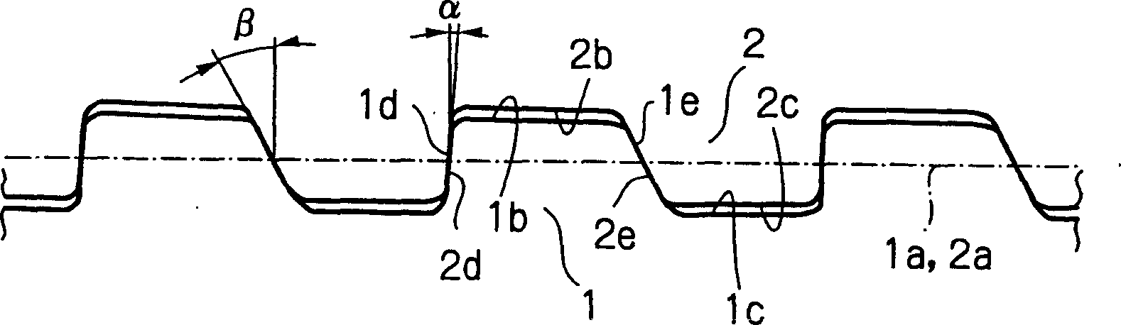
[0058] like image 3 As shown, in order to manufacture a thread in which both the load flank and the stab flank are in contact, a situation is depicted in which both surfaces are in contact due to the coincidence of the pitch diameters in a state where the threads have been engaged. Then, the dimensions of each piece can be determined. At this time, if the thread shapes of the external taper thread 1 and the internal taper thread 2 are the same, it becomes easier to determine the size.

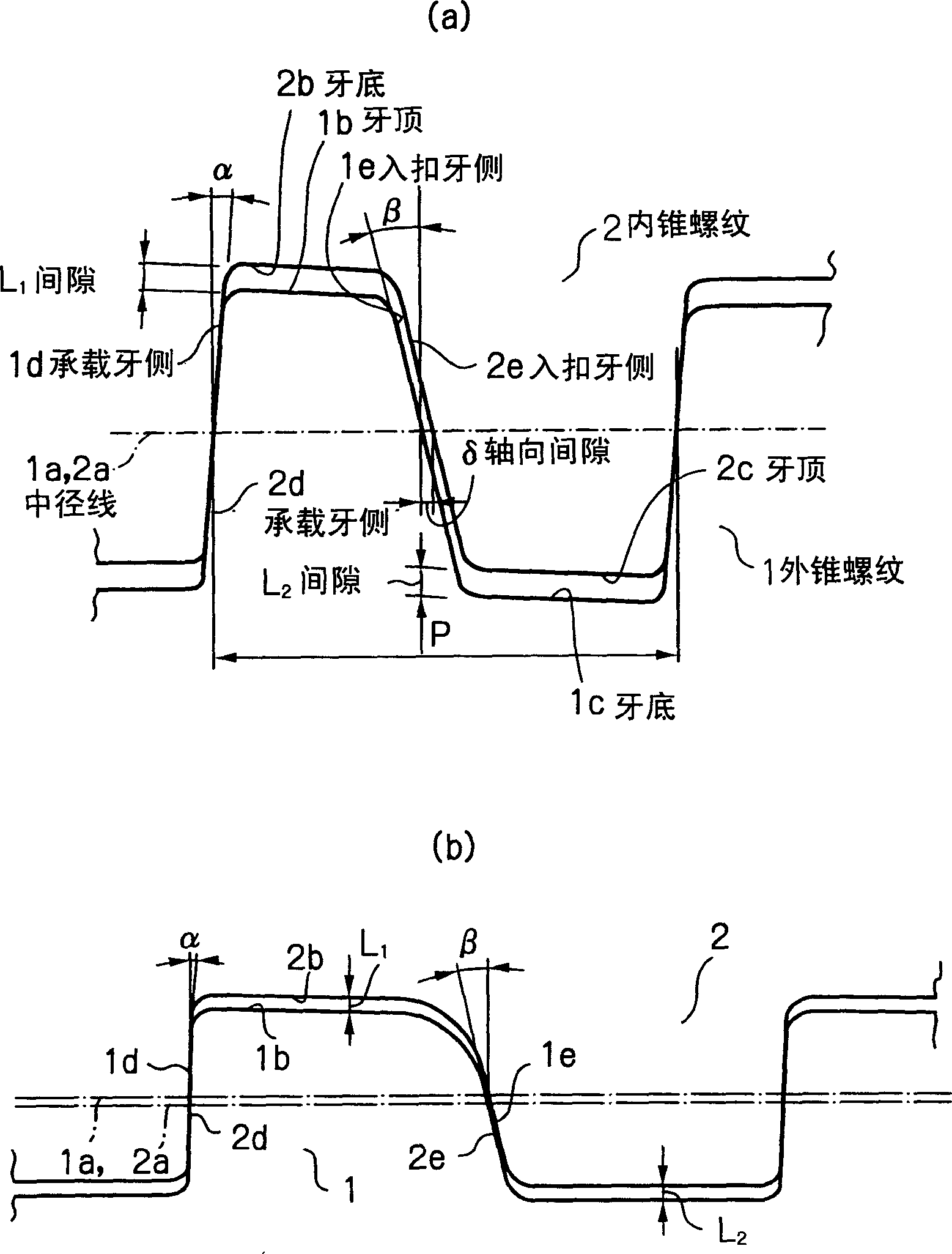
[0059] like Figure 4 (a) and 4(b) and Figure 5 As shown in (a) and 5(b), when the external taper thread 1 and the internal taper thread 2 are designed and drawn separately, the size of each part can be determined after determining the same basic thread shape and size.

[0060] However, during actual manufacturing, dimensional tolerances must be considered during machining. Manufacturing tolerances must be included when determining basic dimensions.

[0061] An embodiment of the present ...


PUM

PropertyMeasurementUnit
Outer diameteraaaaaaaaaa
Yield strengthaaaaaaaaaa

Abstract

The gap L (mm) which is the smaller of the gap L1 (mm) between the crest 1a of a tapered male thread 1 and the root 2b of a tapered female thread 2, and the gap L2 (mm) between the root 1c of the tapered male thread 1 and the crest 2c of the tapered female thread 2, the load flank angle alpha ( DEG ) and the stab flank angle beta ( DEG ), and the axial gap delta (mm) which forms in the widthwise direction and is the difference between the thread ridge width of the tapered male thread 1 and the thread valley width of the tapered female thread 2 threadingly engaged therewith have the following relationship <DF> delta ≤ L.(tan alpha + tan beta ) </DF> When interference of the threaded portions is necessary, the initial set thread interference H is H > 2L. As a result, a thread having sufficient resistance to tensile force and compressive force can be easily manufactured within manufacturing tolerances. In particular, it has good sealing properties and increased reliability as a threaded joint for an oil well pipe having a metal seal portion.

Description

technical field [0001] The present invention relates to a joint with tapered threads for connecting oil well pipes, for example, to each other. Background technique [0002] When the taper thread is connected, the external thread and the internal thread are threadedly engaged with each other. Not only do the load flanks come into contact with each other but also between the crest of the male thread and the root of the female thread, or between the root of the male thread and the crest of the female thread, or the entry on the opposite side (rear side) of the load flank. When contact occurs between the stab flanks, tightening is prevented and relative movement in the radial direction of the thread is also prevented. Normally, when the crest or root of the male thread is in contact with its opposite root or crest, tightening is prevented and further thread engagement between the male and female threads is prevented. [0003] If the tightening force (torque) is further increa...

Claims


Application Information

Patent Timeline
IPC IPC(8): E21B17/042F16L15/06
CPCF16L15/006F16L15/06F16L15/001E21B17/042
Inventor 前田惇永作重夫炭谷胜利
Owner SUMITOMO METAL IND LTD
Why Eureka
Try Eureka