Wireless receiving device and method of controlling antenna beam-width and method thtereof, and base station and mobile communication system

A wireless receiving device, antenna beam technology, applied in diversity/multi-antenna systems, antenna supports/installation devices, antennas, etc., can solve problems such as difficulty in implementing a processing system, increasing the beam width and setting place, and increasing the amount of calculation.

Inactive Publication Date: 2003-08-27
NTT DOCOMO INC
View PDF0 Cites 0 Cited by
  • Summary
  • Abstract
  • Description
  • Claims
  • Application Information

AI Technical Summary

Problems solved by technology

[0008] Among the existing interference mitigation technologies mentioned above, when using a circular aperture antenna, although it is expected to reduce the interference by increasing the antenna aperture, increasing the beam width will bring about the problem of requiring a larger installation space
Also, when the interference is not serious and you want to spontaneously set up two or more links to multiple base stations, sometimes you want to increase the orientation angle, but you cannot meet this requirement
In addition, if the beam width changes, the antenna itself must be replaced
Another disadvantage is that when adding a new line, not only must a real antenna be installed, but also increase the interference received from the new line, and even the antennas of other lines must be replaced
Although it is also possible to deal with new disturbances, there is a problem that it is difficult to configure a processing system due to the complexity of the control, and the amount of calculation increases.
[0010] Also, after all, there are physical and technical limitations on the narrowness of the beam width of the above-mentioned circular antenna and adaptive array antenna, so the influence of the interference wave coming from the same direction as the expected wave is still strong.
[0011] Let’s look at the situation of the interference canceller again. Although all interference waves can be eliminated theoretically, if the number of interference waves increases, a copy generation circuit is required for each interference wave, so the circuit scale and calculation amount will increase. Exponentially growing, difficult to implement processing systems

Method used


Image

  • Wireless receiving device and method of controlling antenna beam-width and method thtereof, and base station and mobile communication system
  • Wireless receiving device and method of controlling antenna beam-width and method thtereof, and base station and mobile communication system
  • Wireless receiving device and method of controlling antenna beam-width and method thtereof, and base station and mobile communication system

Examples


Embodiment Construction

[0031] Embodiments of the present invention will be described in detail below in conjunction with the accompanying drawings.

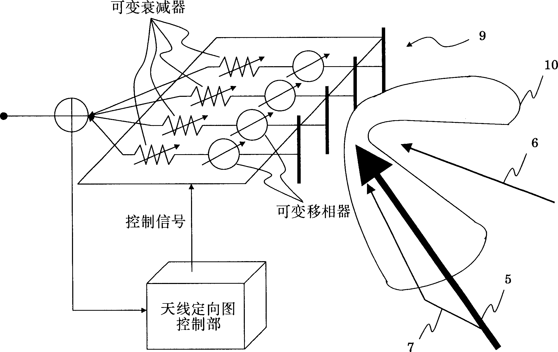
[0032] Figure 5 A block diagram of a wireless receiving device 50 according to an embodiment of the present invention is given. The variable beam width antenna 56 may be a phased array antenna composed of a plurality of units. The beam width or emission pattern of the phased array antenna is mainly controlled by the phase of the excitation factor of each receiving element. Unlike the adaptive array antenna, the phased array antenna does not carry out height calculation control to direct the null (NULL) toward the direction of the arrival of the interference wave, but only performs control to change the directional direction and beam width, so it has the excellent effect of less processing. Generally, not only the directivity direction but also the beam width can be changed with variable directivity antennas, but in the present invention, any antenna...


PUM


Abstract

A radio receiver is provided with a beam-width-variable antenna that receives a radio signal and is capable of changing the beam-width; an interference canceller for removing interference waves from the received radio signal and outputting an interference-wave-removed signal; a measuring device for measuring reception quality of the received signal based on the interference-wave-removed signal; and a beam-width controller for controlling the beam-width of the beam-width-variable antenna based on the reception quality from the measuring device.

Description

technical field [0001] The present invention relates to a wireless receiving device and method, in particular to a wireless receiving device and a wireless receiving device characterized by controlling the beam width (or orientation angle) of a variable beam width antenna according to the reception quality such as the ratio of the received desired wave power to the interference wave power. method. Background technique [0002] In a mobile communication system such as a cellular phone system, a radio entrance network (radio entrance network) connecting base stations must be established. figure 1 Such a wireless communication system is exemplified. [0003] according to figure 1 , each base station 2 forming each service area 1 has an antenna 4 with directivity 3 . The wireless incoming network between the base stations 2 is established through the directional antenna 4 (refer to figure 1 thick arrow). In this wireless inter-station access network, the antenna 4 not only ...

Claims


Application Information

Patent Timeline
Patent Type & Authority Applications(China)
IPC IPC(8): H01Q1/24H01Q3/26H01Q3/28H01Q3/30H01Q25/00H04B1/10H04B7/10
CPCH01Q3/28H01Q1/246H01Q3/2611H01Q25/00H01Q3/00
Inventor 前田浩次油川雄司大津彻
Owner NTT DOCOMO INC
Why Eureka
Try Eureka