Accelerated speed sensor

An acceleration sensor, acceleration technology, applied in the measurement of acceleration, speed/acceleration/impact measurement, acceleration measurement using inertial force, etc., can solve the problems of inability to make the thickness thin, the insulation resistance drops, the polarization drop, etc., to improve the voltage Sensitivity, reduction in manufacturing cost, effect of reduction in the number of electrodes

Inactive Publication Date: 2003-09-10
MURATA MFG CO LTD
View PDF0 Cites 6 Cited by
  • Summary
  • Abstract
  • Description
  • Claims
  • Application Information

AI Technical Summary

Problems solved by technology

However, if there is concern about the decrease in insulation resistance as described above, the thickness of each layer cannot be made thin, so it is difficult to improve the sensitivity.
[0007] As mentioned above, when the layers are connected in series, the advantage is that the voltage sensitivity is high, but there is also a problem that the polarizati

Method used


Image

  • Accelerated speed sensor
  • Accelerated speed sensor
  • Accelerated speed sensor

Examples


Embodiment Construction

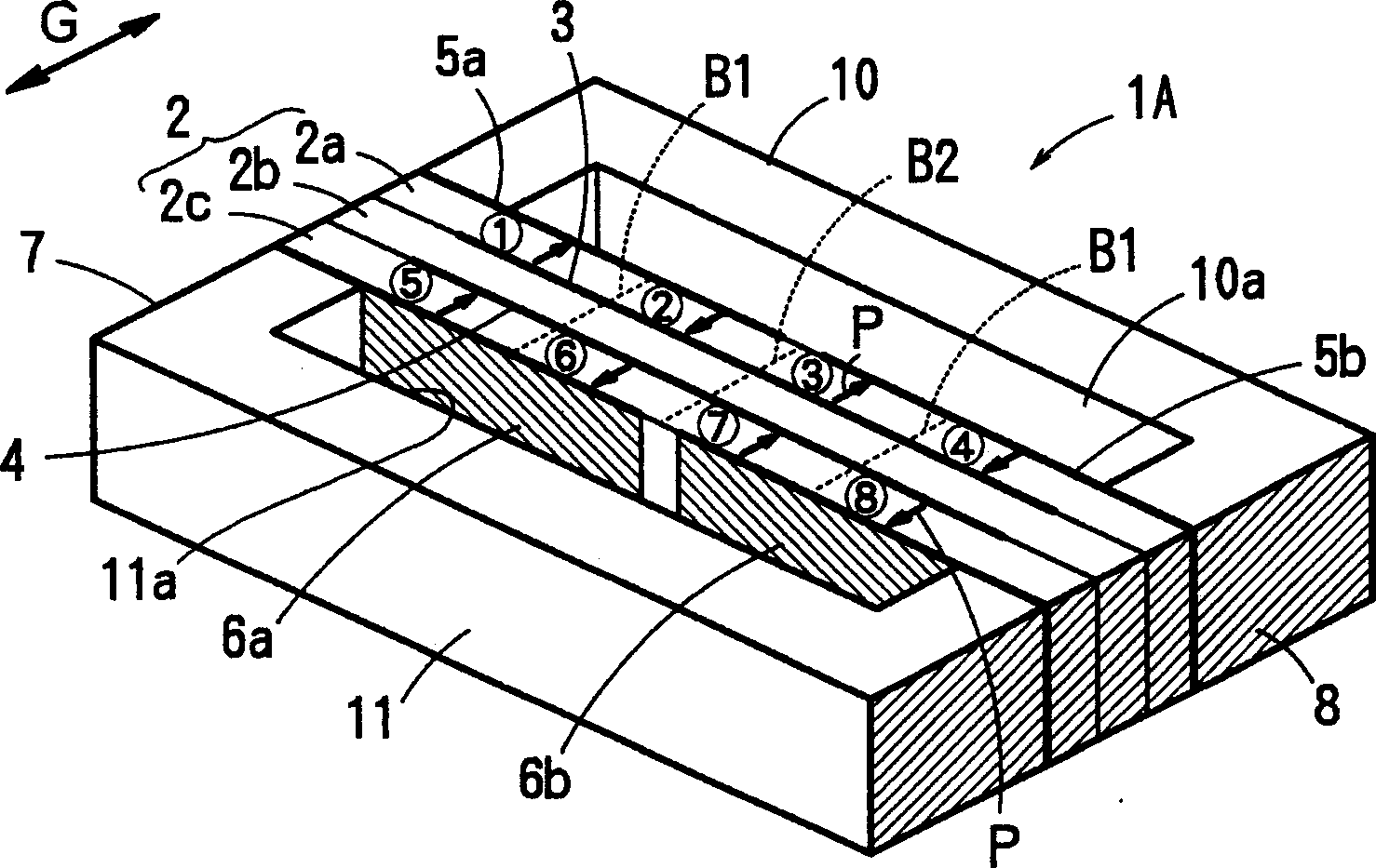
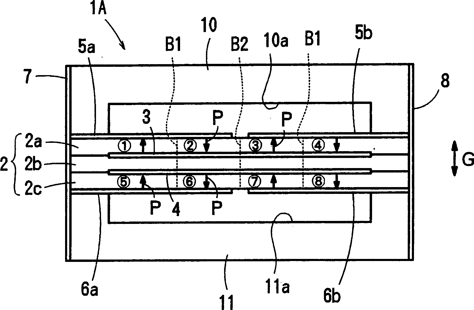
[0041] Figure 1 to Figure 5 A first embodiment of the acceleration sensor of the present invention is shown.

[0042]In this acceleration sensor 1A, both ends in the longitudinal direction of the piezoelectric element 2 are supported from both ends by a pair of support frames (support members) 10 and 11 having a U-shaped cross section. The support frames 10 and 11 are formed using the piezoelectric element 2 and insulating ceramics having approximately the same thermal expansion coefficient, or the like. Recesses 10a, 11a are formed on the inner surfaces of the support frames 10, 11 so that the piezoelectric element 2 can obtain a bending space under the action of the acceleration G.

[0043] In the piezoelectric element 2 of this embodiment, three layers of piezoelectric bodies 2a, 2b, and 2c made of piezoelectric ceramics having a thin rectangular shape and a thin wall are laminated and sintered into one body. The thicknesses of the three layers may be the same, and the o...


PUM


Abstract

An accelerated speed sensor (1A) having a high voltage sensitivity and capable of preventing reduction of polarization due to pyroelectric effect, comprises a piezoelectric element (2) and support members (10, 11) for supporting the piezoelectric element at both longitudinal ends thereof, the piezoelectric element is laminated with three piezoelectric layers (2a, 2b, 2c), each of the two outer piezoelectric layers (2a, 2c) are longitudinally divided into four units (1)-(4), (5)-(8), respectively, when being applied accelerated speeds. Interlayer electrodes (3, 4) and main surface electrodes (5a, 5b, 6a, 6b) are provided on the piezoelectric element (2) so that two cells (1, 2, 5, 6) on one side of the piezoelectric element and two cells (3, 4, 7, 8) on the other side are connected respectively, and the parallel-connected two sets of cells on the two sides are connected in series. The electrodes (5a, 6a), (5b, 6b) induced to different ends of the piezoelectric element (2) are connected with each other.

Description

technical field [0001] The present invention relates to an acceleration sensor using a piezoelectric element. Background technique [0002] Conventionally, as acceleration sensors using piezoelectric ceramics, such as Figure 11 As shown in (a), the piezoelectric element 20 having a bimorph structure in which two self-piezoelectric ceramic layers 21 and 22 are placed in close contact with each other and connected in series is held by one side. 23 and 24 are main surface electrodes, 25 is an interlayer electrode, 26 is a supporting portion, and 27 and 28 are extraction electrodes. Figure 11 (b) is a circuit diagram. In this case, the polarization directions P of the layers 21 and 22 are reversed in the thickness direction so that the voltages generated when the acceleration G is applied can be added. [0003] In the acceleration sensor having such a structure, when the temperature changes, a voltage is generated on each layer 21, 22 due to the pyroelectric effect. [0004]...

Claims


Application Information

Patent Timeline
IPC IPC(8): G01P15/09
CPCG01P15/0922
Inventor 多保田纯
Owner MURATA MFG CO LTD
Why Eureka
Try Eureka