Large power generator stator winding terminal part vibration on line monitoring method

A generator stator and winding end technology, applied in the direction of instruments, etc., can solve problems such as unfavorable computer analysis records, complicated receiving equipment, and failure to obtain the direction of vibration, etc., achieve large market application prospects, solve economic losses, and simple design Effect

Inactive Publication Date: 2003-09-17
SHANGHAI JIAO TONG UNIV
View PDF1 Cites 30 Cited by
  • Summary
  • Abstract
  • Description
  • Claims
  • Application Information

AI Technical Summary

Problems solved by technology

However, there are obvious defects in this patented technology. Because it uses a grating, its sensitivity is not high
The generator stator vibration measurement system made by this technology cannot mea

Method used


Image

  • Large power generator stator winding terminal part vibration on line monitoring method
  • Large power generator stator winding terminal part vibration on line monitoring method
  • Large power generator stator winding terminal part vibration on line monitoring method

Examples


Embodiment Construction

[0016] The technical solution of the present invention will be further described below in conjunction with the accompanying drawings.

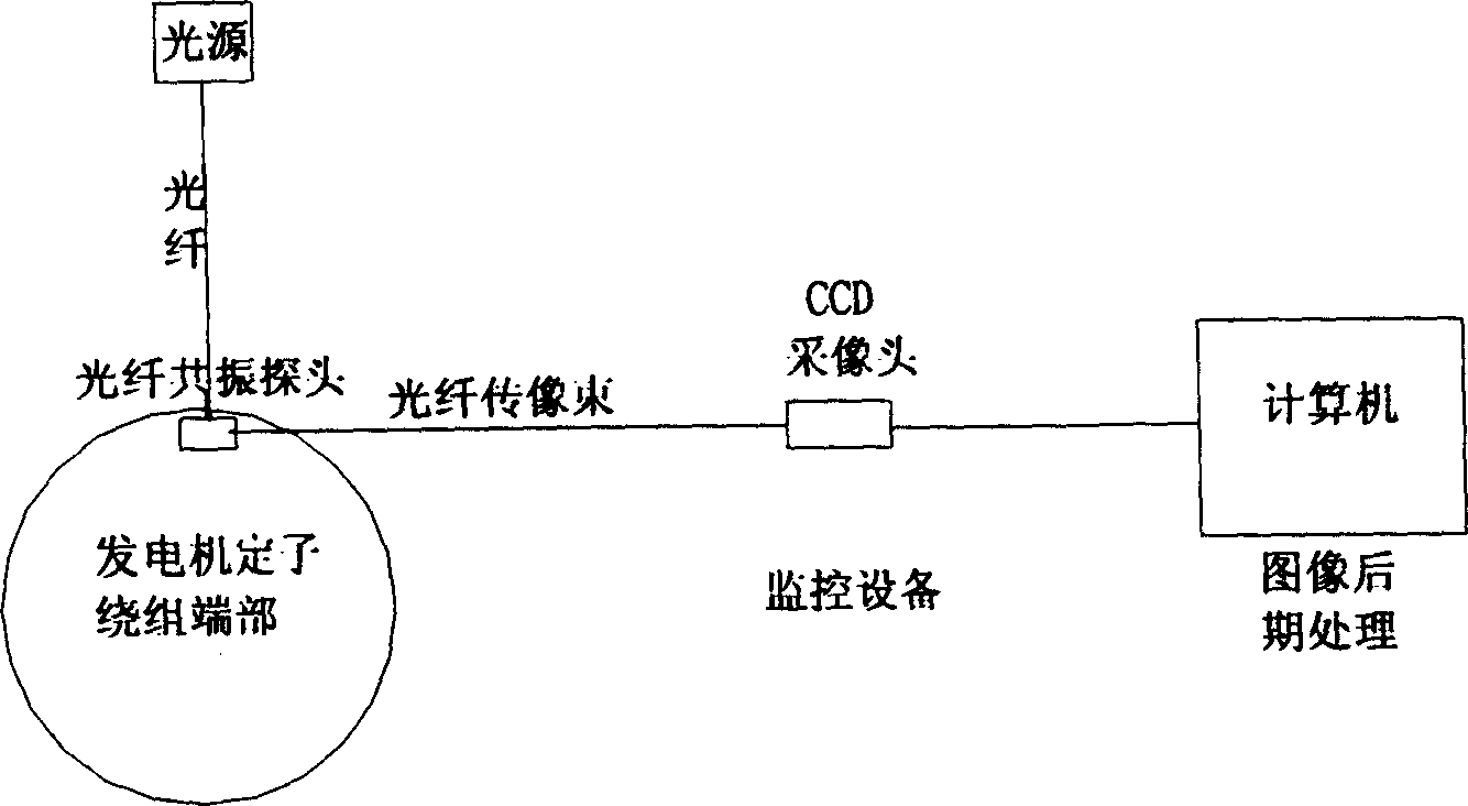
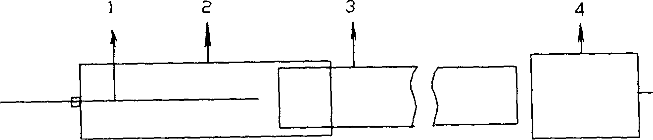
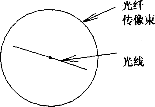
[0017] The present invention uses the method of optical fiber resonance to monitor the vibration state of the generator stator winding end on-line. The process is as follows: figure 1 Shown. An optical fiber resonance probe is installed at the end of the generator stator winding. The structure and transmission principle of the optical fiber resonance probe are as follows figure 2 Shown. In the optical fiber resonance probe, the fixed end of the vibrating fiber 1 is connected to an external light source, and the circular fiber image transmission bundle 3 is placed at a distance from the free end of the vibrating fiber. The resonance probe protective sleeve 2 transmits the images of the resonant fiber 1 and the optical fiber image bundle 3 The receiving ends are fixed together. The optical fiber image transmission bundle 3 is connected to an exter...


PUM


Abstract

An in-line monitoring method for the end vibration of stator windings of large electric generator is based on the resonance characteristics of optical quartz fibre. An optical fibre probe for detecting resonance is arranged at the end of said stator winding. In said probe ,the vibrating fibre is coupled to external light source and the imaging fibre cluster is coupled to external CCD cameral head. The vibration image is received by said CCD camera head and then processed by computer to obtain the amplitude and direction of vibration.

Description

Technical field: [0001] The invention relates to an on-line monitoring method for the end vibration of the stator winding of a large generator, which utilizes the resonance characteristics of a quartz optical fiber and adopts an optical fiber resonance probe to monitor the vibration condition of the end of the stator winding of a large generator on-line. Background technique: [0002] Due to the large workload and continuous operation of large generators, the internal stator of the generator is prone to various faults. Due to the internal high voltage (close to 20,000 volts) and strong magnetic field, it is difficult to apply ordinary detection technology. The generator factory can only carry out some basic maintenance work without knowing the internal conditions of the generator. In order to prevent major accidents, it is generally necessary to shut down the operation for maintenance in about three years in China. At present, if a large generator is shut down for maintenance, it...

Claims


Application Information

Patent Timeline
IPC IPC(8): G01M7/00
Inventor 郭晓金殷宗敏曹美全
Owner SHANGHAI JIAO TONG UNIV
Why Eureka
Try Eureka