
Plug socket for pin grid array plug-in board

A pin array and socket technology, applied in the field of sockets, can solve the problems of inability to align electronic plug-ins of different sizes

Inactive Publication Date: 2003-09-24
TE CONNECTIVITY CORP
View PDF0 Cites 1 Cited by
  • Summary
  • Abstract
  • Description
  • Claims
  • Application Information

AI Technical Summary

Problems solved by technology

This poses a problem to the current sockets, which can only be aligned with a single size of electronic plug-in and cannot be aligned with electronic plug-ins of different sizes.
This requires the use of different receptacles to accommodate different sized electronic inserts, and if the electronic insert used in the electrical system is changed, the receptacle must also be changed, resulting in more parts, time, expense and inconvenience associated with changing the receptacle

Method used


Image

  • Plug socket for pin grid array plug-in board
  • Plug socket for pin grid array plug-in board
  • Plug socket for pin grid array plug-in board

Examples


Embodiment Construction

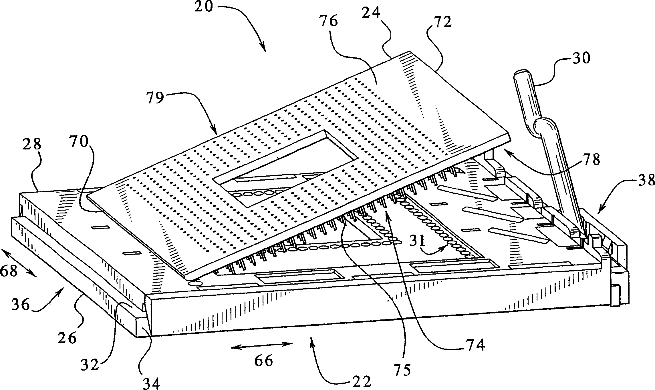
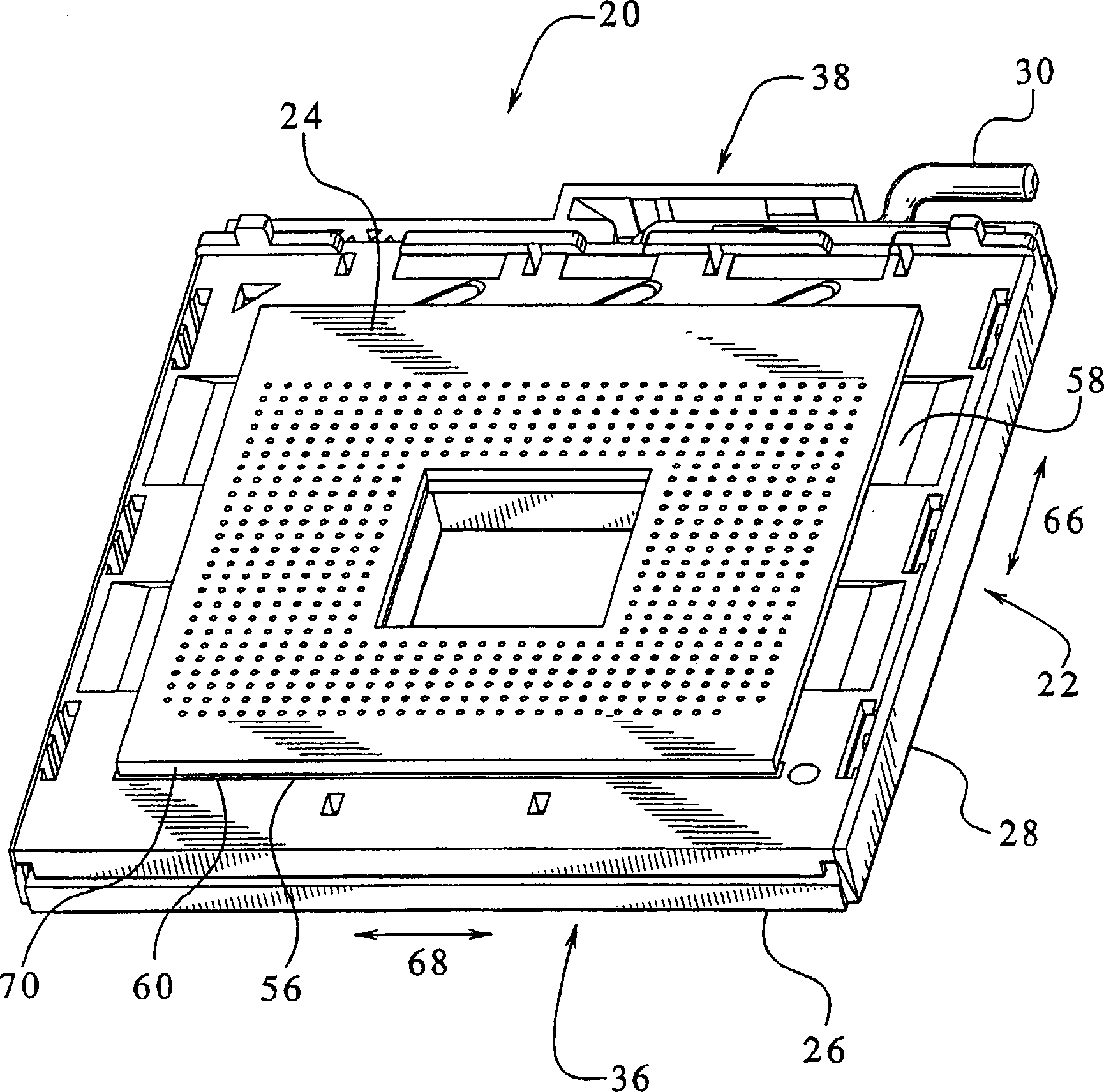
[0024] figure 1 An embodiment of the PGA component 20 when the first electronic package 24 is mated with the socket 22 is shown, figure 2 A fully mated PGA component 20 is illustrated. The receptacle 22 includes a base housing 26 , a cover 28 and a handle 30 . Cover 28 is slidably engaged with base housing 26 . The handle 30 is rotatable between open and closed positions and is used to manipulate the sliding movement of the cover 28 over the base housing 26 using a cam mechanism (not shown). figure 1 , the handle 30 is in the open position. figure 2 , the handle 30 is in the closed position. Before mating, the handle 30 is in the open position. Then, the first electronic package 24 is placed on the cover 28 such that the holes of the cover 28 accept the pins of the first electronic package 24 . With the handle 30 in the open position and the first electronics package 24 assembled on the cover 28 , the needles of the first electronics package 24 extend through the cover...


PUM


Abstract

A socket (22) is provided for accepting an electronic package (24) having an array of pins (75) and a type having different first and second dimensions. The receptacle includes: a base housing (26) having a top surface and an array of needle-receiving chambers in the top surface; and a cover (28) slidably fitted over the base housing. The cover has a top surface to receive an electronic package on the top surface and an array of holes through the cover corresponding to the array of pins. A first locator is provided to align the pins of the electronic package having a first size with the array of holes in the cover, and a second locator is provided to align the pins of the electronic package having a second size with the array of holes in the cover .

Description

technical field [0001] The invention basically relates to a socket that can accept electronic components of different sizes. Background technique [0002] Pin grid array (PGA) sockets are used to accept electronic packages on printed circuit boards. The PGA socket facilitates electrical communication between a large number of pins on an electronic package, such as a microprocessor, and the electrical component that the PGA socket is equipped with. Zero-mating-force PGA sockets use a cover that slides between open and closed positions on the base. For example, a handle may be used to actuate the sliding. The cover has an array of holes configured to match the array of pins on the electronics package. Similarly, the base has an array of pin-receiving chambers configured to receive the array of pins of the electronic package. The electronics package is mated to the receptacle by first positioning the electronics package so that its pins pass through the holes in the cover. ...

Claims


Application Information

Patent Timeline
IPC IPC(8): H05K7/10
CPCH05K7/1007
Inventor 戴维·A·特劳特理查德·N·怀尼
Owner TE CONNECTIVITY CORP
Learn More