Multiple-cutting-edge cutter-bit and multiple-cutting-edge cutter-bit type cutting tool

A cutting tool and blade technology, applied in the field of multi-edged blades, can solve problems such as blade damage, blade offset, damage to the processing surface, etc., to achieve the effects of preventing precision, stable and smooth cutting, and improving installation rigidity

Inactive Publication Date: 2003-10-01
MITSUBISHI MATERIALS CORP
View PDF1 Cites 20 Cited by
  • Summary
  • Abstract
  • Description
  • Claims
  • Application Information

AI Technical Summary

Problems solved by technology

However, in the above-mentioned insert, the side is formed in a straight line connecting the second cutting edge, so that, as described above, even if the side is formed to be inclined slightly inward in the radial direction, as the above-mentioned second cutting edge is approached, The distance between the blade side and the vertical wall will gradually narrow, so, especially in the case of processing with the above-mentioned axis as the transverse direction, the chips will bite into the narrowed space and damage the processed surface ( vertical wall) or risk of blade breakage
In addition, the blade body is formed into a polygonal plate shape, and the two adjacent side surfaces of the corner portion at the position of the diagonal line of the second cutting edge are clamped and fixed after abutting against the supporting surface of the blade body. , but since the abutment of these faces is the abutment between planes, it is difficult to ensure the installation of the insert with respect to the change in the direction of the cutting load acting on the insert, especially in the case of forming a flat part and forming a vertical wall. Rigid, there is a risk of misalignment on the blade

Method used


Image

  • Multiple-cutting-edge cutter-bit and multiple-cutting-edge cutter-bit type cutting tool
  • Multiple-cutting-edge cutter-bit and multiple-cutting-edge cutter-bit type cutting tool
  • Multiple-cutting-edge cutter-bit and multiple-cutting-edge cutter-bit type cutting tool

Examples


Embodiment Construction

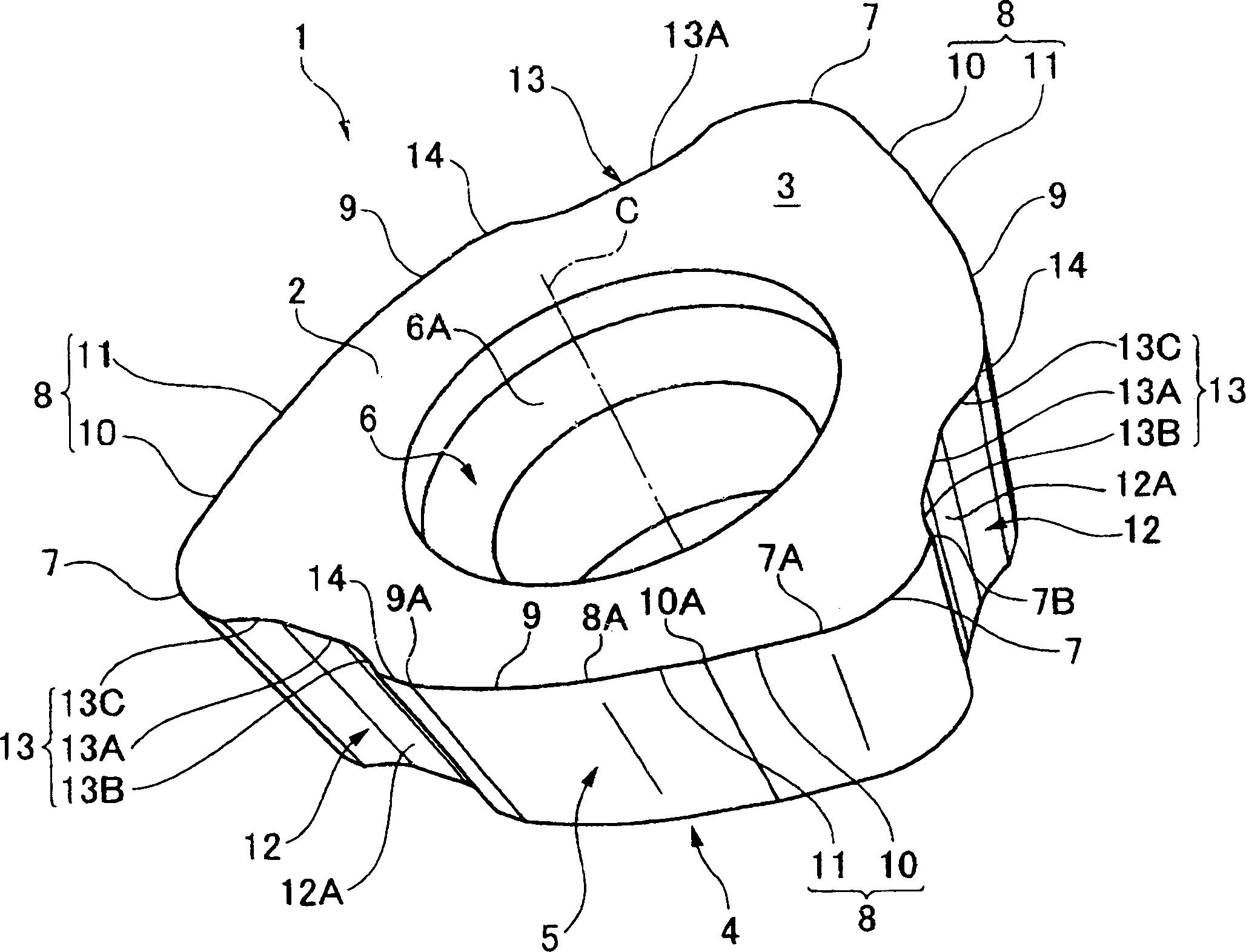
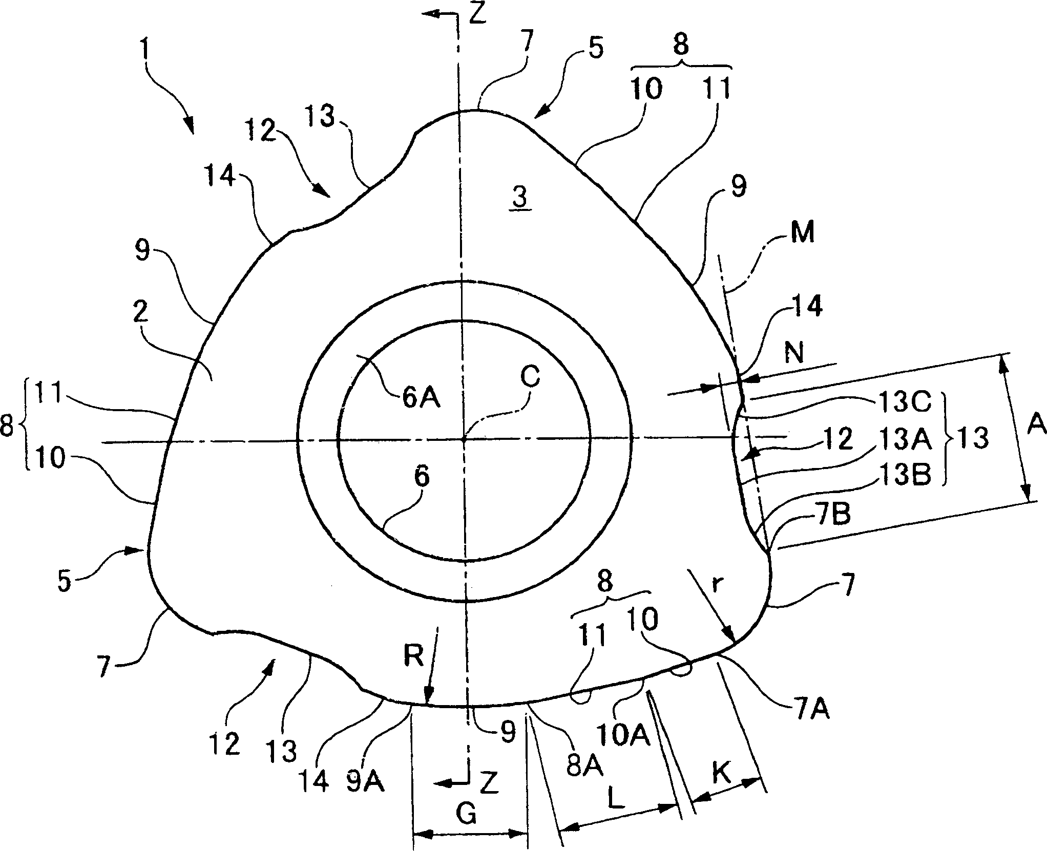
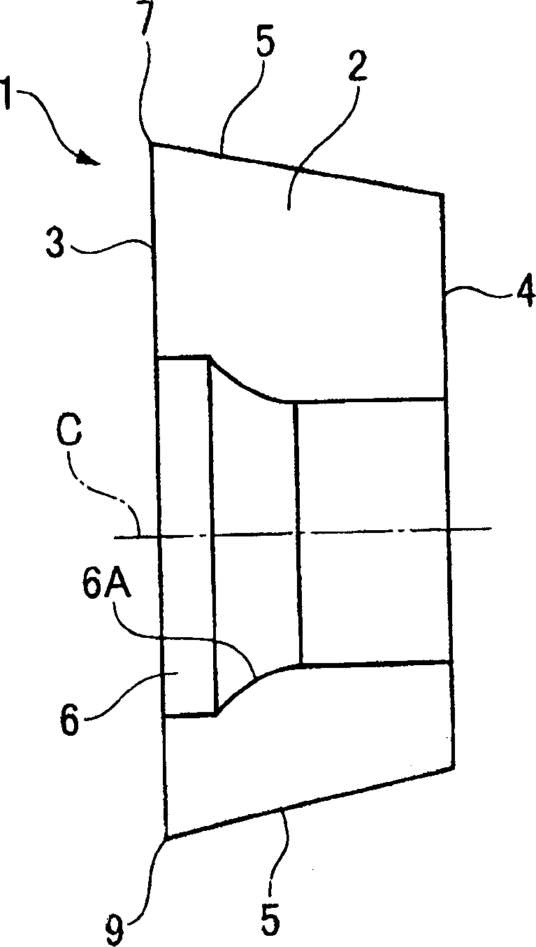
[0027] Figure 1 to Figure 4 It is a figure which shows the blade 1 of 1st Embodiment of this invention. The blade 1 of this embodiment forms its blade main body 2 with hard materials such as cemented carbide alloys, and its profile is a roughly equilateral triangle (more specifically, a hexagonal) plate shape, constituting one face of a roughly equilateral triangle as the front The rake face 3 and the other face serve as a support face 4 parallel to the rake face. In addition, a relief face 5 is formed on the sides around the rake face 3 and the support face 4. Cutting edges are formed on intersecting ridgeline portions of the rake face 3 , that is, edge portions of the rake face 3 . In addition, the insert 1 of the present embodiment is a positive insert with an edge bevel on the relief surface 5 by intersecting the rake surface 3 and the relief surface 5 via cutting edges to form an acute angle. In other words, the support surface 4 is formed into a similar shape that is ...


PUM


Abstract

A throwaway insert (1) comprises an insert body (2) formed in a polygonal shape, a cutting face (3) formed by a polygonal face of the insert body (2), a corner cutting edge (7) which is formed in a curved shape at a corner of the cutting face (3), a major cutting edge (8) which is formed along a side edge of the cutting face (3) that is connected to a first end (7A) of the corner cutting edge (7), and a concave portion (13) which is formed, in another side edge of the cutting face (3) that is connected to a second end (7B) of the corner cutting edge (7), so as to be adjacent to the second end (7B) of the corner cutting edge (7), and so as to be made concave toward the inside of the cutting face (3) from a tangent (M) of the corner cutting edge (7) drawn at the second end (7B) of the corner cutting edge (7). By using the throwaway insert (1), cut chips are prevented from being packed in a gap between the throwaway insert (1) and a surface (V) being machined, and the fixing rigidity of the throwaway insert (1) is increased.

Description

technical field [0001] The present invention relates to a multi-edged insert (hereinafter referred to as "insert") detachably attached to a multi-edged insert type cutting tool (hereinafter referred to as "cutting tool"), and to a cutting tool to which the insert is attached. Background technique [0002] As such an insert and a cutting tool, the inventors of the present invention have proposed an insert and a cutting tool in JP-A-2000-141123. It includes a first cutting edge (main cutting edge) with a specified length, and a second cutting edge (corner edge) with a small radius of curvature that is continuous with the radial direction outside of the first cutting edge with respect to the axis of rotation. State, giving the first cutting edge a prescribed chamfer angle, the blade is detachably installed in such a way as to protrude from the outer periphery of the blade body, and the cutting tool is a kind of blade mounted thereon, by turning around the above-mentioned axis ...

Claims


Application Information

Patent Timeline
Patent Type & Authority Applications(China)
IPC IPC(8): B23B27/14B23C5/20B23C5/22
CPCB23C5/2243B23C2200/0416B23C2200/0477B23C2200/201B23C2210/66Y10T407/23Y10T407/2268Y10T407/1908Y10T407/245B23C5/2213B23C5/202B23C5/20
Inventor 长屋秀彦池永幸一林崎弘章
Owner MITSUBISHI MATERIALS CORP
Why Eureka
Try Eureka