
Horizontal rotary compressor

A rotary compressor and rotary compression technology, which is applied in the direction of rotary piston machinery, rotary piston pumps, mechanical equipment, etc., can solve problems such as the inability to smoothly achieve oil suction, and achieve the effect of eliminating obstacles

Inactive Publication Date: 2003-10-01
SANYO ELECTRIC CO LTD
View PDF0 Cites 7 Cited by
  • Summary
  • Abstract
  • Description
  • Claims
  • Application Information

AI Technical Summary

Problems solved by technology

As a result, oil remains not only on the oil pump side, but also on the electric component side, and there is a problem that if the oil level of the oil pump portion drops, the oil cannot be sucked smoothly.

Method used


Image

  • Horizontal rotary compressor
  • Horizontal rotary compressor
  • Horizontal rotary compressor

Examples


Embodiment Construction

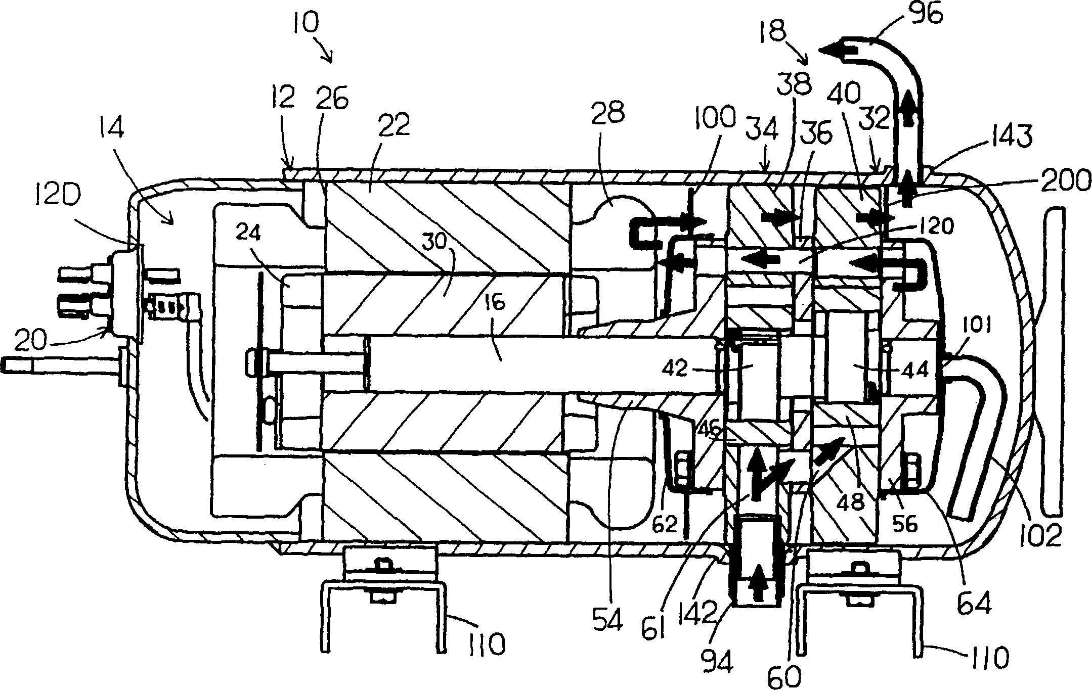
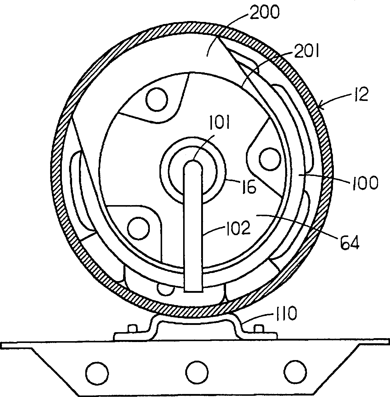
[0017] Embodiments of the present invention will be specifically described below according to the accompanying drawings. figure 1 It is a longitudinally cut side view of an internal high-pressure type horizontal rotary compressor 10 having first and second rotary compression members as an embodiment of the horizontal rotary compressor of the present invention, figure 2 for figure 1 A longitudinally sectioned side view of the rotary compressor 10.

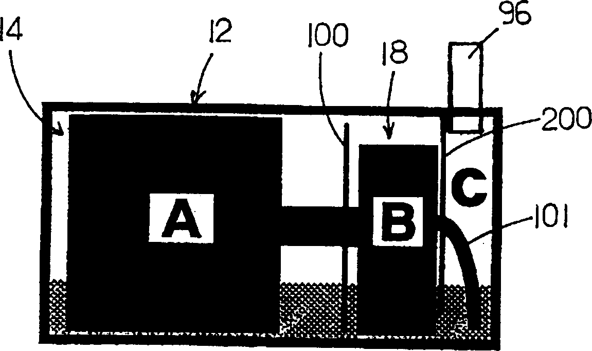
[0018] In each figure, the horizontal rotary compressor 10 of the embodiment is an internal high-pressure type horizontal rotary compressor, which includes a horizontally long cylindrical airtight container 12, and both ends of the airtight container 12 are airtight. The bottom of the airtight container 12 forms an oil storage portion. Inside the airtight container 12, the electric component 14 and the rotary compression mechanism part 18 are accommodated by the first rotary compression component 32 and the second rotary compress...


PUM


Abstract

There is provided a horizontal rotary compressor capable of improving performance thereof while an oil supply means smoothly supplies oil. A part of a hermetic shell case (12) at the upper side is partitioned by a baffle plate (200) into an electric element (14) side and an oil pump (101) side, a refrigerant which is drawn from an outside of the hermetic shell case (12) is compressed by a first rotary compression element (32) and a second rotary compression element (34) and discharged toward the electric element (14) side of the baffle plate (200), then it is further discharged from oil pump (101) side toward the outside of the hermetic shell case (12). The baffle plate (200) closes a flow path area of the refrigerant over an oil level inside the hermetic shell case (12) at a ratio ranging from not less than 50% to not more than 80% during the stoppage of the horizontal rotary compressor. <IMAGE>There is provided a horizontal rotary compressor capable of improving performance thereof while an oil supply means smoothly supplies oil. A part of a hermetic shell case (12) at the upper side is partitioned by a baffle plate (200) into an electric element (14) side and an oil pump (101) side, a refrigerant which is drawn from an outside of the hermetic shell case (12) is compressed by a first rotary compression element (32) and a second rotary compression element (34) and discharged toward the electric element (14) side of the baffle plate (200), then it is further discharged from oil pump (101) side toward the outside of the hermetic shell case (12). The baffle plate (200) closes a flow path area of the refrigerant over an oil level inside the hermetic shell case (12) at a ratio ranging from not less than 50% to not more than 80% during the stoppage of the horizontal rotary compressor. <IMAGE>

Description

technical field [0001] The present invention relates to a horizontal rotary compressor that discharges refrigerant gas compressed by a rotary compression unit into an airtight container. Background technique [0002] This conventional horizontal rotary compressor is constructed in such a way that the refrigerant gas is sucked into the low-pressure chamber side of the cylinder from the suction port of the rotary compression unit, compressed by the action of the rollers and vanes, and released from the cylinder The side of the high-pressure chamber, through the exhaust port, the exhaust muffler, is discharged into the inside of the airtight container, and then flows into the external radiator and the like. In addition, an oil storage part is formed at the bottom of the airtight container, and the oil is sucked from the oil storage part through the oil pump (oil supply mechanism) installed on the opposite side of the rotary compression part to the electric part, and supplied to...

Claims


Application Information

Patent Timeline
Patent Type & Authority Applications(China)
IPC IPC(8): F04C18/356F04C23/00F04C29/02
CPCF04C23/001F04C23/008F04C29/028F04C18/00
Inventor 山中正司鸟山悦男竹中学小暮吉久
Owner SANYO ELECTRIC CO LTD
Learn More