
Ultrasonic linear motor

A linear motor, ultrasonic technology, applied in the direction of generator/motor, piezoelectric effect/electrostrictive or magnetostrictive motor, circuit, etc. Satisfied with the walking ability of the movable guide rail

Inactive Publication Date: 2003-10-15
OLYMPUS CORP
View PDF3 Cites 7 Cited by
  • Summary
  • Abstract
  • Description
  • Claims
  • Application Information

AI Technical Summary

Problems solved by technology

[0031] However, although the previous proposal described in the above-mentioned Japanese Patent Application Laid-Open No. 9-19172 can reduce the size of the ultrasonic vibrator or the size of the pressing device, since the ultrasonic vibrator itself is not a self-propelled structure, the actual moving pair The movable guides, or the ball bearings that allow these movable guides to slide, and the plates connected to the movable guides, etc. are indispensable, the number of parts is large, the manufacturing process is complicated, and for this reason, it is not possible to meet the miniaturization of ultrasonic linear motors
And, considering the operational performance of the ultrasonic linear motor, only a part of the peripheral surface of the circular ultrasonic vibrator is in contact with the movable guide rail, and it is difficult to fully exert the driving force generated by the ultrasonic elliptical vibration of the ultrasonic vibrator. structure, and as a result, there is a possibility that satisfactory running performance of the movable guide rail cannot be obtained
[0032] And, as mentioned above, the previous proposal described in the above-mentioned Japanese Patent Laid-Open No. 7-163162 can only move the driven body of the ultrasonic linear motor in one direction, and in order to reduce the friction during the movement, it is necessary to use a cross roller. Therefore, even if the size of the ultrasonic vibrator, the size of the pressing device, or the size of the driven body is reduced, the overall size becomes larger, and as a result, the device cannot be miniaturized.

Method used


Image

  • Ultrasonic linear motor
  • Ultrasonic linear motor
  • Ultrasonic linear motor

Examples


Embodiment Construction

[0057] Objects and advantages of the present invention will be more apparent from the following detailed description.

[0058] Embodiments of the present invention will be described below with reference to the drawings.

[0059] 1st embodiment

[0060] structure

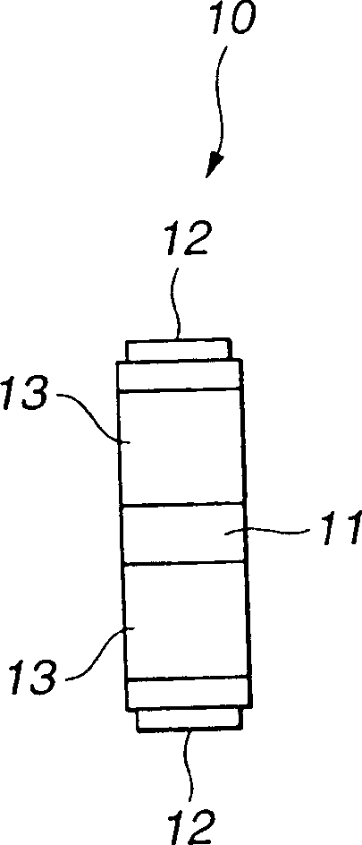
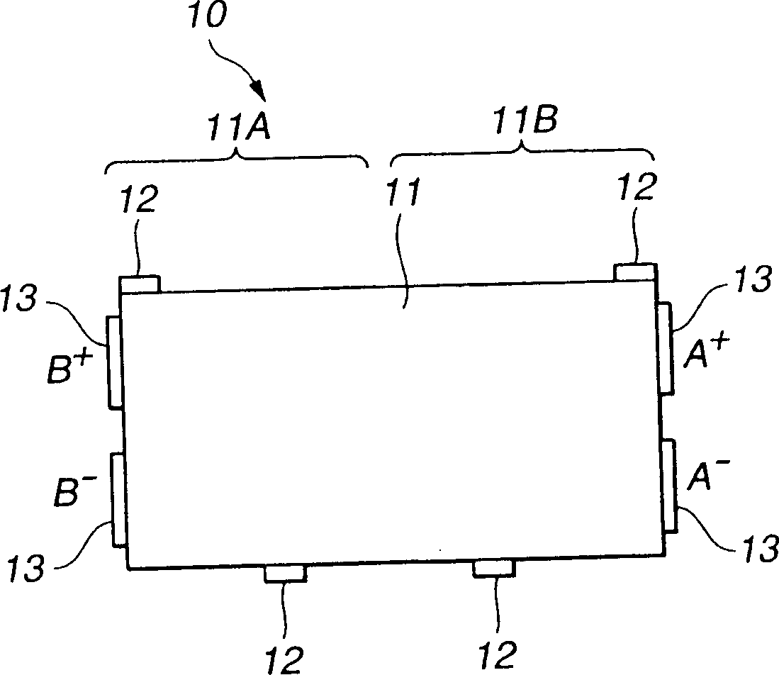
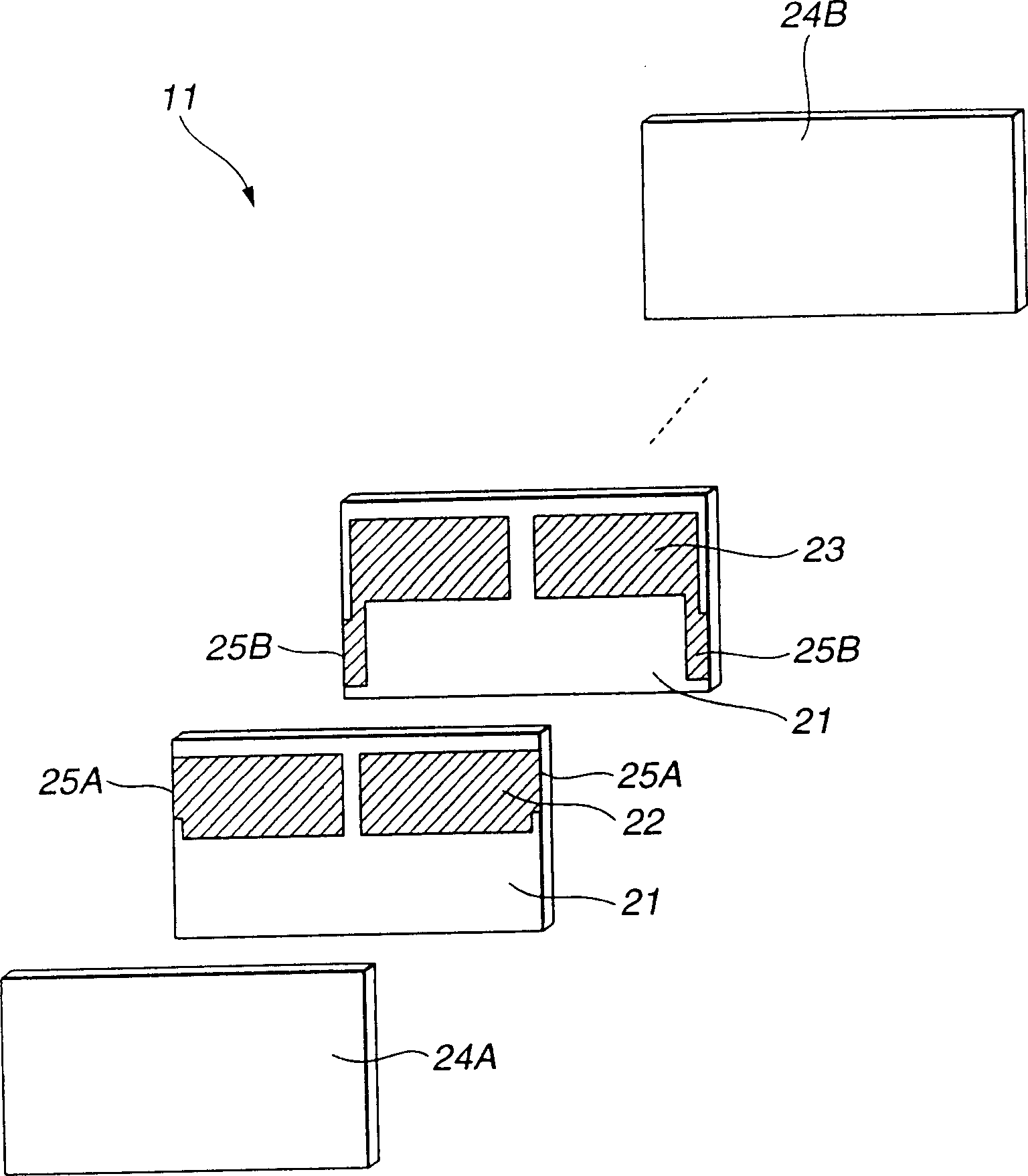
[0061] 1 to 5 show a first embodiment of an ultrasonic linear motor according to the present invention. FIG. 1 is an explanatory diagram illustrating a schematic structure of an ultrasonic vibrator mounted on the ultrasonic linear motor, and FIG. 1(A) shows the ultrasonic vibration The front view of the device, Figure 1 (B) is the side view of the ultrasonic vibrator, figure 2 It is an exploded perspective view showing in detail the main part of the basic part of the ultrasonic vibrator shown in FIG. 1, and FIG. 3 is a perspective view showing the operating state of the ultrasonic vibrator of the present embodiment, and FIG. , Figure 3(B) shows the resonant bending vibration state. 4 is an explanatory diagram fo...


PUM


Abstract

The ultrasonic linear motor (30) of the present invention constitutes the ultrasonic vibrator (10) by bonding the driver (12) on the opposite face of the ultrasonic vibrator (10) and at a position opposite to the rotation direction of the elliptical vibration, and a pair of The guide device (31) contacted by the driver (12) is provided with an ultrasonic vibrator (10) therebetween, and a plate spring (34) as a pressing device for mutual traction is arranged between the pair of guide devices (31), A self-propelled ultrasonic linear motor constituting the self-propelled ultrasonic vibrator. Thereby, not only the running performance of the ultrasonic vibrator itself can be improved, but also the miniaturization of the ultrasonic linear motor can be realized.

Description

technical field [0001] The present invention relates to an ultrasonic linear motor using an ultrasonic vibrator, and more particularly to an ultrasonic linear motor capable of miniaturization with a simple structure. Background technique [0002] In recent years, ultrasonic motors have attracted attention as a new type of motor replacing electromagnetic motors. Compared with the previous electromagnetic motor, such an ultrasonic motor has the following advantages: [0003] (1) Since there are no gears, low-speed high-thrust can be obtained. [0004] (2) Great holding power. [0005] (3) Long stroke and high resolution. [0006] (4) Good quietness. [0007] (4) Does not generate magnetic noise and is not affected by noise. [0008] As a conventional linear ultrasonic motor having such advantages, there are ultrasonic vibrators disclosed in Japanese Patent Application Laid-Open No. 7-163162 and ultrasonic linear motors using the ultrasonic vibrator proposed by the present...

Claims


Application Information

Patent Timeline
IPC IPC(8): H02N2/00H01L41/09H02N2/08
CPCH02N2/026H01L41/083H01L41/0913H10N30/2023H10N30/50
Inventor 舟洼朋树佐佐木靖夫登坂清荻野兵治川岛隆中尾寿宏
Owner OLYMPUS CORP
Learn More