

Non-continuous double diagonal internal rib reinforced heat exchange tube
A technology of inclined inner rib and heat exchange tube, applied in the direction of heat exchanger shell, tubular element, heat exchange equipment, etc., can solve the problems of low processing efficiency, large flow resistance and high manufacturing cost, and achieve simple molding and small flow resistance. , Good anti-fouling effect
- Summary
- Abstract
- Description
- Claims
- Application Information
AI Technical Summary
Problems solved by technology
Method used
Image

Examples
Embodiment 1
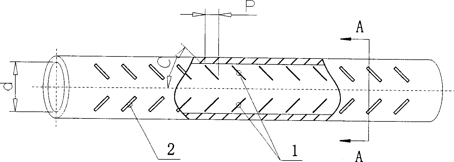
[0018] figure 1 It is a structural schematic diagram of a discontinuous double inclined internal rib enhanced heat exchange tube. The inner side of the tube has a discontinuous bidirectional helical protrusion (abbreviated as "discontinuous bidirectional helical inner rib"), and the outer side of the tube has a discontinuous bidirectional helical groove.
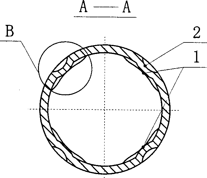
[0019] figure 2 for figure 1 A-A sectional view in .
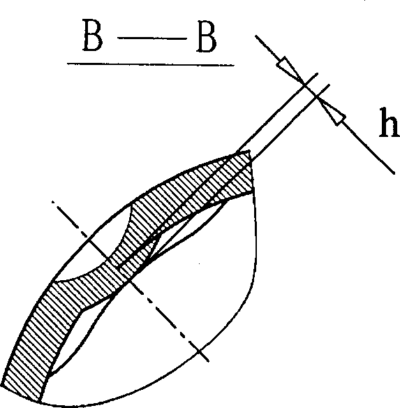
[0020] image 3 for figure 2 Partial enlarged view of B in middle.
[0021] exist figure 1 and figure 2 Among them, 1 is the discontinuous two-way helical rib inside the tube, and 2 is the discontinuous two-way helical groove outside the tube; the helical rib and the helical groove are formed simultaneously during processing. figure 1 where d is the hydraulic inner diameter of the heat exchange tube, P is the axial length of a single double-slope inner rib, and C is the helix angle of the double-slope inner rib. image 3 where h is the height of the double ob...
Embodiment 2
[0023] Figure 4 It is a schematic diagram of part of the circumferentially expanded structure of another discontinuous double inclined internal rib enhanced heat exchange tube. The inside of the tube has discontinuous two-way spiral protrusions (double oblique inner ribs), and the outside of the tube is a smooth wall.
[0024] Figure 4 Among them, 3 is a discontinuous two-way spiral rib and is symmetrically arranged; a right-handed diagonal rib and a circumferentially adjacent left-handed diagonal rib form a vortex generator; in the same cross section, there are 4 diagonal ribs along the circumferential direction to form two vortex generators . Figure 4 C is the helix angle of the double oblique inner rib, C≈±50 degrees; a positive value means right-handed, and a negative value means left-handed, where C is the right-handed angle. Figure 4 Among them, 4 is a schematic illustration of the longitudinal vortex generated by the fluid near the inner wall under the action of ...
Embodiment 3
[0026] Figure 5 It is a schematic diagram of another kind of discontinuous double inclined internal rib enhanced heat exchange tube, which is partly developed in the circumferential direction. The inner side of the tube has discontinuous two-way helical protrusions (double oblique inner ribs), and the outer side of the tube has discontinuous two-way helical grooves.
[0027] Figure 5 Among them, 5 is a discontinuous two-way helical rib inside the tube and is arranged asymmetrically, 6 is a discontinuous two-way helical groove outside the tube and is asymmetrically arranged; a right-handed oblique rib in the pipe and a circumferentially adjacent left-handed oblique rib form a vortex generator; There are six oblique ribs on the inner wall of a small section of pipe (less than 0.5d) to form three vortex generators.
[0028] The best implementation of the discontinuous double-slope internal rib heat exchange tube is rolling or molding. The rolling and rolling forming process ...
PUM
 Abstract
Description
Claims
Application Information