Fin type heat exchanger of gas-liquid partition wall pipes with pin ribs
A fin heat exchanger and needle fin technology, which is applied in the field of strengthening heat exchange and heat exchangers, can solve the problems of high flow resistance, high pump power, large flow resistance, etc., to achieve enhanced heat transfer, high compactness, Material saving effect
- Summary
- Abstract
- Description
- Claims
- Application Information
AI Technical Summary
Problems solved by technology
Method used
Image
Examples
Embodiment 1
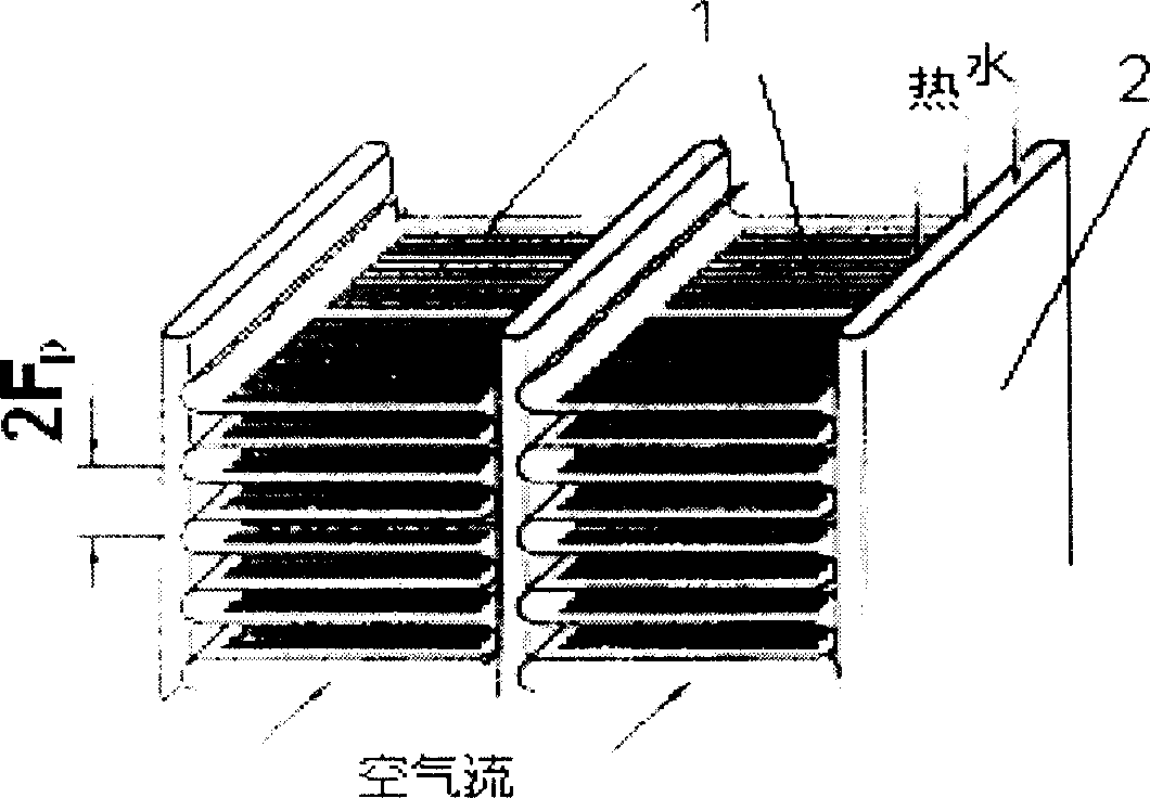
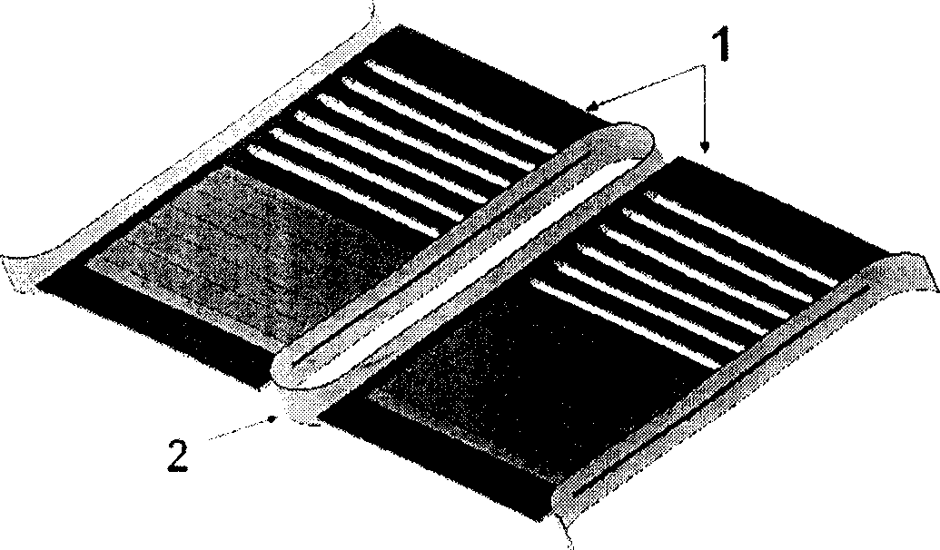
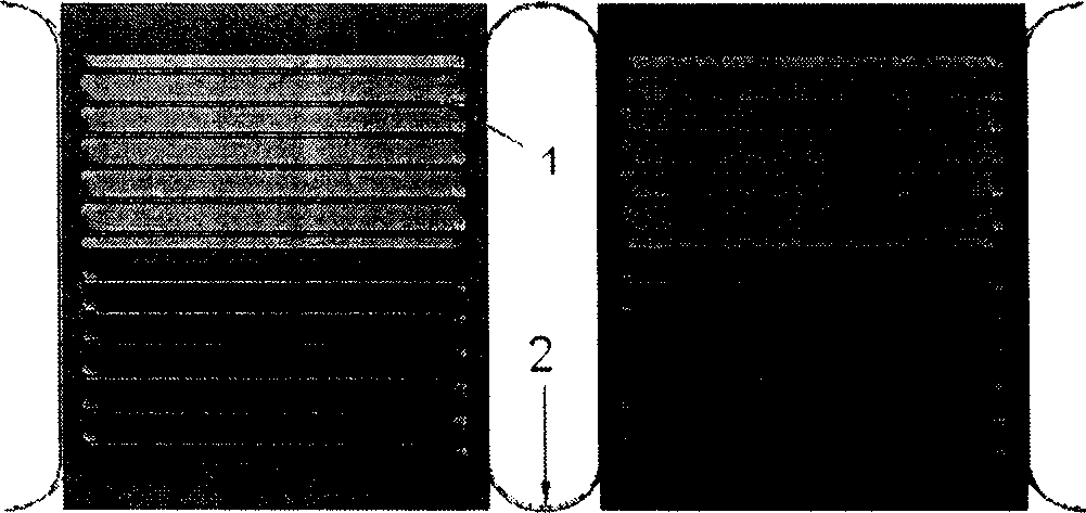
[0033] Figure 6 ~ Figure 8 It is a schematic diagram of a periodic unit structure of a tube-fin heat exchanger with cylindrical pin fins, followed by Figure 1 ~ Figure 4 It can be seen from comparison that it replaces the louver fins with cylindrical pin fins on the basis of the existing structure of the tube-belt heat exchanger, and connects them between the walls of the liquid tubes. Every 4 ribs are arranged in a group, and each group is arranged in a staggered manner. According to the length of the gas flow direction, 7 and a half groups are arranged, and the number of pin ribs is 30. according to figure 2 The geometric parameters shown are respectively: d=0.2mm, Fp=1.0mm, S1=S2=0.4mm, S3=0.5mm, flow direction length Fd=17mm.
[0034] The simulation is carried out with water and air, and the simulation results of its flow resistance and air-side heat transfer coefficient are listed in Table 2 and Table 3, corresponding to PF in Table 2 and Table 3 1 structure. It ca...
Embodiment 2
[0036] Figure 9It is a schematic diagram of a periodic unit structure of a tube-fin heat exchanger with regular hexagonal prism pin fins, similar to Example 1, which replaces the louver fins with regular hexagons on the basis of the existing structure of the tube-belt heat exchanger The prism pin fins are connected between the walls of the liquid pipe. Every 4 ribs are arranged in a group, and each group is arranged in a dislocation, and 7 groups are arranged according to the length of the gas flow direction, and the number of pin ribs is 28. according to Figure 5 The geometric parameters shown are: side length S=0.11mm, Fp=1.2mm, S1=0.4mm, S2=0.8mm, S3=0.5mm, Fd=17mm.
[0037] The simulation is carried out with water and air, and the simulation results of its flow resistance and air-side heat transfer coefficient are listed in Table 2 and Table 3, corresponding to PF in Table 2 and Table 3 2 structure. The results show that the air side heat transfer coefficient h of th...
Embodiment 3
[0039] Figure 10 It is a schematic diagram of a periodic unit structure of a tube-fin heat exchanger with regular octagonal prism pin fins, similar to Example 1, which replaces the louver fins with regular octagonal prism pin fins on the basis of the existing structure of the heat exchanger , connected between the walls of the liquid pipe. Every 4 ribs are arranged in a group, and each group is arranged in a dislocation, and 7 groups are arranged according to the length of the gas flow direction, and the number of pin ribs is 28. according to Figure 5 The geometric parameters shown are: side length S=0.1mm (area about 0.0314mm2), F p =1.0mm, S1=0.4mm, S2=0.8mm, S3=0.5mm, F d =17mm.
[0040] The simulation is carried out with water and air, and the simulation results of its flow resistance and air-side heat transfer coefficient are listed in Table 2 and Table 3, corresponding to PF in Table 2 and Table 3 3 structure. , the results show that the air side heat transfer co...
PUM
| Property | Measurement | Unit |
|---|---|---|
| Diameter | aaaaa | aaaaa |
Abstract
Description
Claims
Application Information
 - R&D
- Intellectual Property
- Life Sciences
- Materials
- Tech Scout
- Unparalleled Data Quality
- Higher Quality Content
- 60% Fewer Hallucinations
Browse by: Latest US Patents, China's latest patents, Technical Efficacy Thesaurus, Application Domain, Technology Topic, Popular Technical Reports.
© 2025 PatSnap. All rights reserved.Legal|Privacy policy|Modern Slavery Act Transparency Statement|Sitemap|About US| Contact US: help@patsnap.com


