Electric detonator initiator

An electric detonator and foot wire technology, used in detonators, electric fuzes, fuzes, etc., can solve the problems of low material utilization rate of refined galvanized thin steel strips, speed up the corrosion rate of welded joints, and reduce resistance stability. The effect of improving electrochemical corrosion resistance, reducing manufacturing process links and reducing scrap rate

Inactive Publication Date: 2003-11-05
顾杨
View PDF0 Cites 13 Cited by
  • Summary
  • Abstract
  • Description
  • Claims
  • Application Information

AI Technical Summary

Problems solved by technology

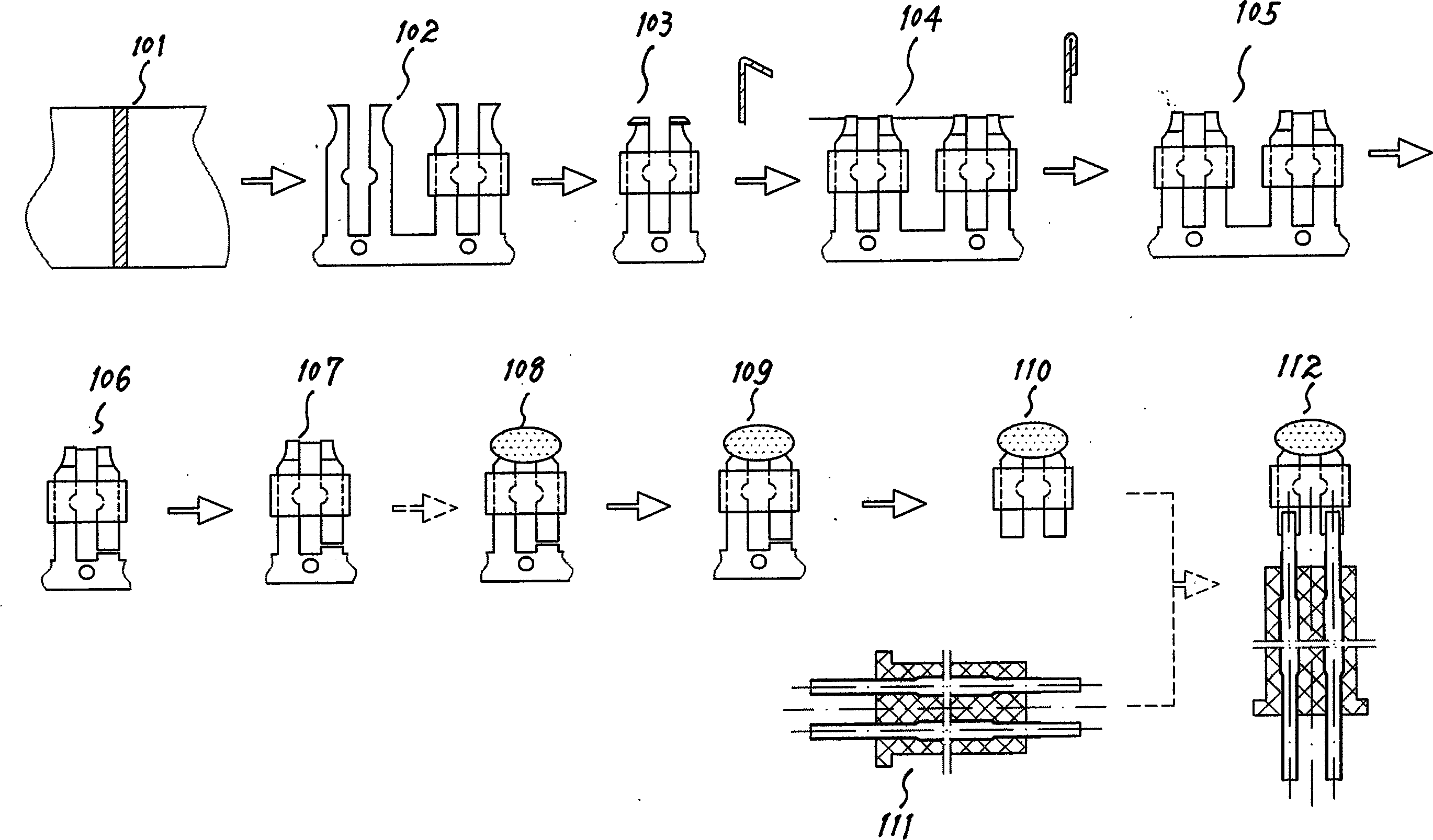
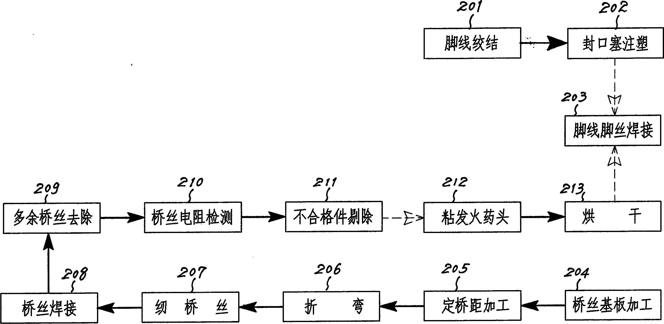
There are following deficiencies in the product obtained by the above-mentioned process: (1) complex production process; (2) expensive production cost; (3) after the refined galvanized thin steel strip is punched, the punched position without galvanized layer is directly exposed, The effect of the chemical primary battery will accelerate the corrosion rate of the welded joints and reduce the stability of the resistance; (4) The material utilization rate of the refined galvanized thin steel strip is low; (5) The foot wire and the bridge wire substrate need to be welded separately; ( 6) It is very difficult to organize product production according to the serial production method, and there are many bottleneck factors in the production process when the product production is organized according to the parallel production method

Method used


Image

  • Electric detonator initiator
  • Electric detonator initiator
  • Electric detonator initiator

Examples


Embodiment Construction

[0022] The present invention will be described in further detail below in conjunction with the accompanying drawings and specific embodiments.

[0023] like Figure 3-1 and Figure 3-2 As shown, the electric detonator ignition device of the present invention includes a bridge wire 305, a foot wire 304 with a plastic sheath 302, a bridge distance fixing device 303 and a sealing plug 301, and the base wire 304 and the bridge wire 305 are integrated structure, so that a foot wire 304 from the sealing plug 301 to the welding end of the bridge wire 305 forms a foot wire, and the foot wire is a variable cross-section structure, and the sections are flat. In the ignition device of the electric detonator of the present invention, the segments shown in the legs are flat sections, and the flat sections are located in the sealing plug 301 section of the legs, the bridge distance fixing device 303 section and the welding end 306 respectively. It can be seen that the fundamental differen...


PUM


Abstract

The electric detonator initiator includes bridge filaments, pin wires, span determinator and sealing plug. The pin wires are integral with the base board for the bridge filaments, and each piece of pin wires is formed with one section of pin wire from the sealing plug to the bridge filament welding end and is variable flat cross section structure. The pin wires have their flat parts inside sealing plug, span determinator and welding end. Both the sealing plug and the span determinator are linked structure with several parts. The present invention has simple production process, and the electric detonator initiator has small dispersion of bridge filaments and high side rigidity.

Description

technical field [0001] The invention relates to an ignition device, in particular to an electric detonator ignition device. Background technique [0002] At present, the main structure of the electric detonator ignition device in the prior art includes a bridge wire, a foot wire, a bridge distance fixing device and a sealing plug, but the base boards of the foot wire and the bridge wire are independent of each other, and the whole production process of the product is as follows: figure 1 shown. Firstly, the galvanized thin steel strip 101 is subjected to fine blanking forming (made of silk substrate) and fixed bridge distance processing 102, then the end is bent 103, and threaded for compaction; then, bridge wires are welded 104, and excess bridge wires are cut off After 105, bridge wire resistance detection 107 is carried out; then, the propellant tip is sticky 108, and the tip is dried 109; finally, the bridge wire substrate 110 cut off at the end of the process and the s...

Claims


Application Information

Patent Timeline
Patent Type & Authority Applications(China)
IPC IPC(8): C06C7/02F42C11/00
Inventor 顾杨
Owner 顾杨
Why Eureka
Try Eureka