Digital hand wheel for valve

A digital wheel, hand wheel technology, applied in valve details, valve device, valve operation/release device and other directions, can solve problems such as inability to accurately control flow, achieve convenient fluid flow, save energy and resources, accurate rotation angle or the effect of laps

Inactive Publication Date: 2003-11-26
王林秋
View PDF0 Cites 4 Cited by
  • Summary
  • Abstract
  • Description
  • Claims
  • Application Information

AI Technical Summary

Problems solved by technology

[0004] The purpose of the present invention is to solve the problem that the valve handwheel cannot accurately control the flow rate, and to provide a valve digital hand

Method used


Image

  • Digital hand wheel for valve
  • Digital hand wheel for valve
  • Digital hand wheel for valve

Examples


Embodiment Construction

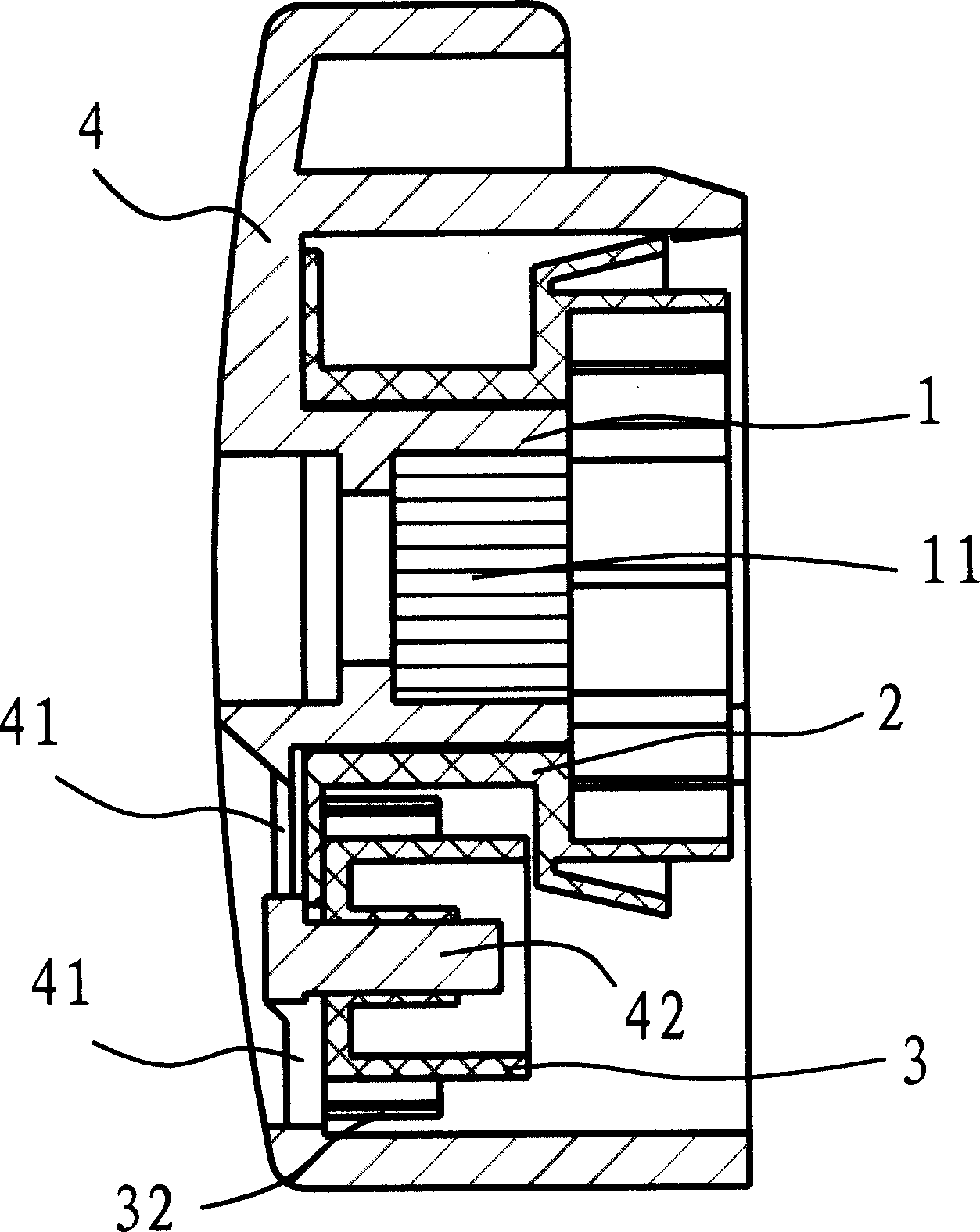
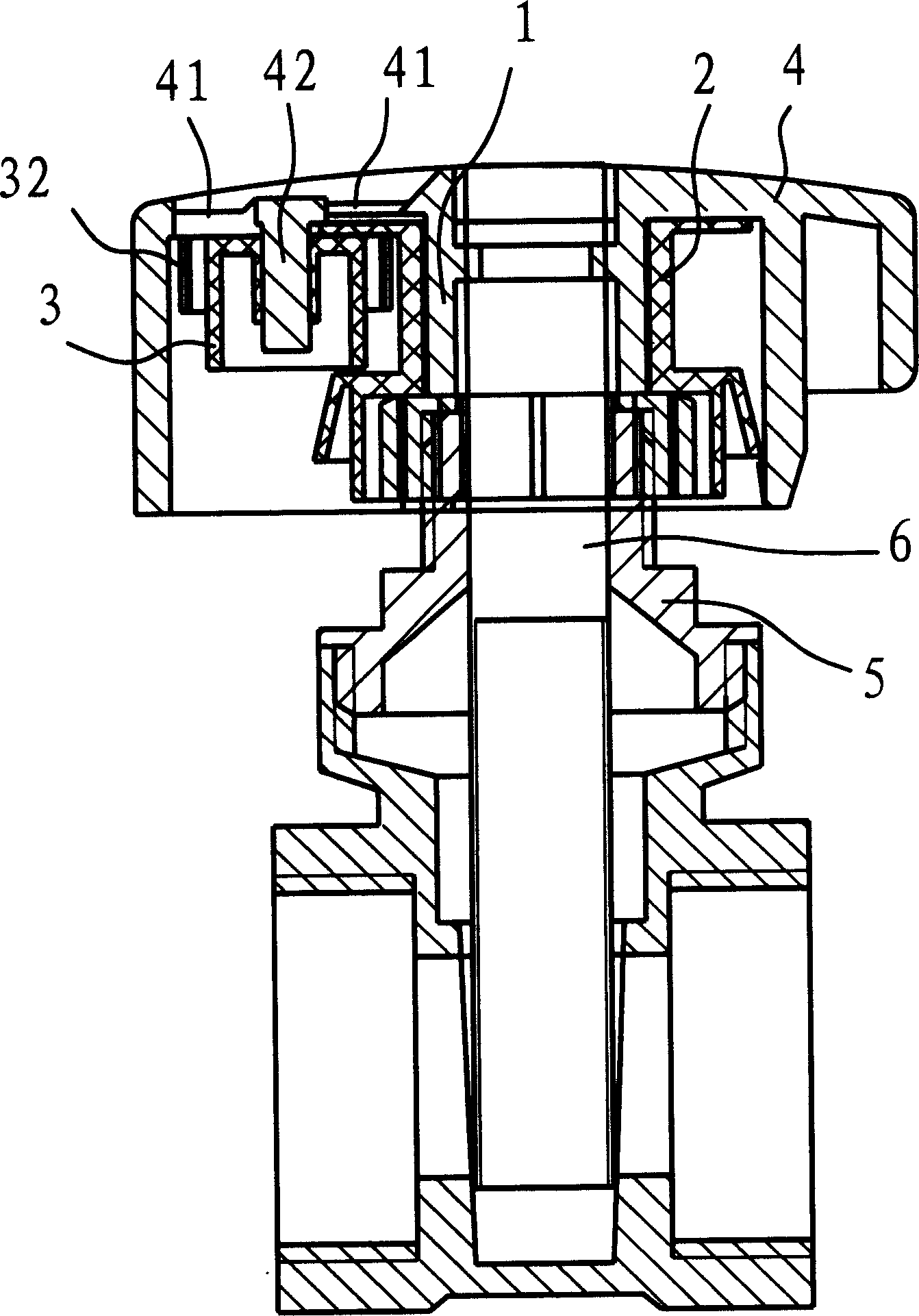
[0026] Such as figure 1 As shown, in this embodiment, the valve digital handwheel is composed of a body 1, a main digital wheel 2, a secondary digital wheel 3, and a casing 4. The main body 1 is cylindrical, and the main number wheel 2 is sleeved on the main body 1 . Teeth 11 are provided on the inner side of the body 1 to facilitate the solid connection with the valve stem 6 .

[0027] Such as image 3 As shown, when the valve digital handwheel is applied to a gate valve, the body 1 is set on the valve stem 6, and the body 1 is fixedly connected to the valve stem 6 through the teeth 11 on the inner surface of the body 1 . The main digital wheel 2 is fixedly connected with the valve body 5 of the gate valve. Obviously, in the process of turning the handwheel, the main number wheel 2 is not moving.

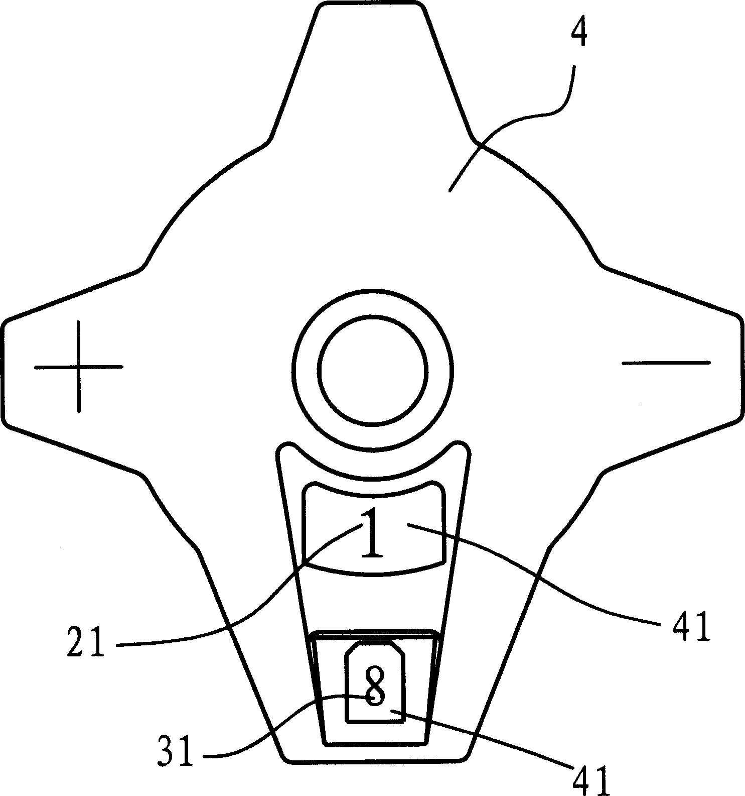
[0028] Such as figure 1 and image 3 As shown, in this embodiment, the secondary digital wheel 3 is arranged on the side of the main digital wheel 2 . Such as Figure 4 to ...


PUM


Abstract

The present invention relates to valve technology. The digital hand wheel for valve includes one main body connected to the valve rod; one main digital wheel connected to valve body, sleeved onto the main body and provided with scale marks; one hood connected to the main body and holding the main body and the main digital wheel; and one auxiliary digital wheel sleeved onto one rotating shaft connected to the main body, provided with scale marks and meshed with the main digital wheel. The digital hand wheel makes the valve intuitively readable for accurate flow rate control, and may be used in various valves, including check valve, gate valve, ball valve, etc.

Description

technical field [0001] The invention belongs to the technical field of valves, in particular to a handwheel used on valves. Background technique [0002] On the valve, a handwheel is generally required to open or close the valve. After the valve is installed in the pipeline, its main function is to control the on-off of the pipeline. But sometimes, it is also necessary to control the flow of fluid in the pipeline through valves to meet various needs. When the existing valves control the flow of pipeline fluid, they all rely on the operator's feeling and experience to complete. In this way, the flow rate of the pipeline is difficult to be accurately controlled, and the deviation is relatively large, which will cause a waste of energy and resources. [0003] At present, there are no digital handwheels or handles with scales on the valves produced and used by people, and no relevant patent documents or technical materials have been seen. Of course, h...

Claims


Application Information

Patent Timeline
IPC IPC(8): F16K31/60F16K37/00
Inventor 王林秋
Owner 王林秋
Why Eureka
Try Eureka