Hybrid compressor system

A compressor system and hybrid technology, applied in the direction of liquid variable capacity machinery, electromechanical devices, mechanical equipment, etc., can solve the problem of increasing the size of the motor and external power supply

Inactive Publication Date: 2003-12-03
DENSO CORP
View PDF1 Cites 15 Cited by
  • Summary
  • Abstract
  • Description
  • Claims
  • Application Information

AI Technical Summary

Problems solved by technology

However, such a motor-driven compression unit requires the motor to be sized in consideration of the maximum cooling capacity of the compression unit (as described above), necessitating an increase in the size of the motor and external power supply

Method used


Image

  • Hybrid compressor system
  • Hybrid compressor system
  • Hybrid compressor system

Examples


no. 1 approach

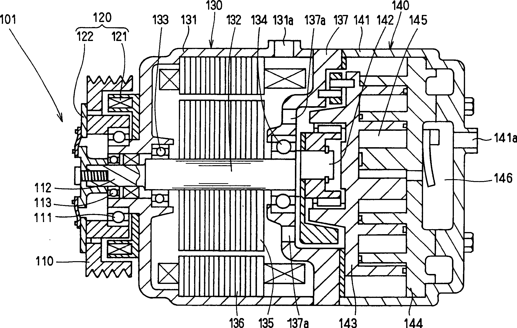
[0047] The following will refer to Figure 1 to Figure 4 Description such as Figure 1 to Figure 8 Shown is a specific structure according to a first embodiment of the invention.

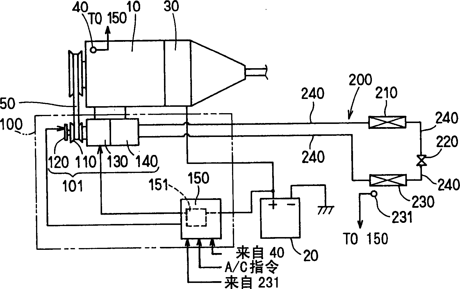
[0048] Such as figure 1 As shown, the hybrid compressor system 100 is applied to a refrigeration cycle system 200 installed in a dual power type vehicle in which a vehicle engine (hereinafter referred to as an engine) 10 is stopped according to its operating conditions. The hybrid compressor system 100 includes a hybrid compressor 101 and a controller 150 serving as a control means. In addition, the dual power type vehicle has a motor generator (generator) 30 directly connected to the engine 10 , which is provided with a rotational speed sensor 40 for detecting the rotational speed of the engine 10 .

[0049] The refrigerating cycle system 200 provides a known refrigerating cycle and is provided with a compression unit 140 which constitutes the hybrid compressor 101, which will be described later...

no. 2 approach

[0077] Figure 9 The second embodiment of the present invention has been described. In the second embodiment, between the pulley 110 and the compressing member 140, more precisely, between the pulley 110 and the motor 130, a gear mechanism is provided as a speed increasing device. In this embodiment, the gear mechanism is embodied as a planetary gear 170 . Among the gears forming the planetary gear 170 , the sun gear 171 is connected to the engine shaft 132 , and the planetary gear 172 is connected to the pulley shaft 112 . A ring gear 173 forming an outer circumferential portion of the planetary gear 170 is fixed to the boss portion 131b near the bottom of the engine frame 131 .

[0078] This configuration enables the rotational speed to provide the maximum displacement required by the engine 10 to operate the compression member 140 . This in turn enables the compression member 140 to provide its smaller displacement per revolution, reducing both the size and manufacturing...


PUM


Abstract

A hybrid compressor system affords maximum cooling capability by making full use of an additional motor to improve the fuel consumption efficiency of a vehicle while ensuring passenger compartment cooling when the engine is stopped. The hybrid compressor system includes a compression unit for compressing a refrigerant, a motor for driving the compression unit, and disconnection means for disconnecting the drive force of a vehicle engine. In the hybrid compressor system, when the thermal load of the refrigeration cycle system lies within a predetermined range in a higher load region, the control means connects the disconnection means to allow the vehicle engine to drive the compression unit. When the thermal load of the refrigeration cycle system lies within a lower load region of the predetermined range, the control means disconnects the disconnection means to allow the motor to drive the compression unit even while the vehicle engine is running.

Description

technical field [0001] The present invention relates to a hybrid compressor system for a refrigerating cycle installed in a dual power type vehicle or an idling-parking vehicle which does not idle for a long time. Background technique [0002] Generally, dual power type or idle-park vehicles have been developed commercially to meet the growing demand for fuel efficient vehicles aimed at reducing the overall consumption of fuel. In these vehicles, the engine is adapted to stop during certain operating conditions (eg, during stationary parking of idle-park vehicles, during stationary parking, low speed operation and start vehicle operation of dual power vehicles). Engine shutdown causes compression components in the engine-driven refrigeration system to stop, resulting in a cessation of air conditioning to the passenger compartment. [0003] To solve this problem, for example, Japanese Patent Laid-Open Publication No. 2000-130323 discloses a hybrid compressor in which the rot...

Claims


Application Information

Patent Timeline
Patent Type & Authority Applications(China)
IPC IPC(8): F04B49/06B60H1/32F04B27/08F04B35/00F04B35/04H02K7/14
CPCB60H2001/3294B60H2001/327F04B35/04B60H1/3222F04B35/002F04B27/0895B60H2001/3266B60H2001/3236B60H1/3208F04B35/00
Inventor 岩波茂树宇野庆一铃木康
Owner DENSO CORP
Why Eureka
Try Eureka