
Lens, combination lens and its mfg. method, optical pickup

A technology of combining lenses and manufacturing methods, applied in the direction of beam guiding devices, optics, lenses, etc., capable of solving problems such as difficulties

Inactive Publication Date: 2003-12-03
SONY CORP
View PDF0 Cites 1 Cited by
  • Summary
  • Abstract
  • Description
  • Claims
  • Application Information

AI Technical Summary

Problems solved by technology

[0043] However, in the mold for forming the above-mentioned first lens assembly that will become the first convex lens L1, there is a first mold M in which continuous aperture portions are respectively provided at positions that will become the first convex lens. 1 and the second mold M 2 , and were inserted into the pin die P 1b and pin die P 1a structure, in order to form the first convex lens L1 with high precision, it is necessary to make the pin mold P 1b and pin die P 1a The central axis is consistent, but, as shown in Figure 7, in the general mold structure, because there is a pin mold P 1b and pin die P 1a The 1st mold M of the continuous aperture part inserted separately 1 With the second mold M 2 are formed separately, and they are combined, so the pin mold P 1b and pin die P 1a The alignment of the central axis of the lens is accompanied by considerable difficulty, and it is difficult to obtain the first convex lens formed with high precision

Method used


Image

  • Lens, combination lens and its mfg. method, optical pickup
  • Lens, combination lens and its mfg. method, optical pickup
  • Lens, combination lens and its mfg. method, optical pickup

Examples


Embodiment approach 1

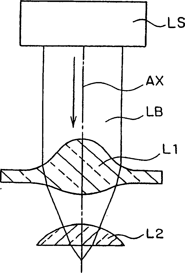
[0099] FIG. 9 is a cross-sectional view showing a schematic configuration of a combined lens (SIL) according to the present embodiment. The SIL is composed of a first convex lens L1 and a second convex lens L2.

[0100] 10A is a perspective view of the first convex lens; FIG. 10B is a perspective view of the second convex lens.

[0101] The first convex lens L1 is composed of the surface of a concave portion 1a with a convex bottom surface on the upper surface of the lens base 1 made of optical materials such as glass and the lower surface of the lens base 1, and the upper surface S of the lens base 1 except for the portion of the concave portion 1a. D and below S A are respectively the planes that should be the datum planes.

[0102] On the other hand, the second convex lens L2 is formed by embedding a material having a higher refractive index than the lens base 2 in a concave portion 2b provided on the lower surface of the lens base 2 made of an optical material such as gl...

Embodiment approach 2

[0124] FIG. 14 is a schematic configuration diagram of an optical pickup device as a main part of an optical disc device according to this embodiment.

[0125] For example, for an optical disk D rotationally driven by a spindle motor SM, a laser diode LD, a collimator C, a 1 / 2 wavelength plate HWP, a beam splitter BS, a 1 / 4 wavelength plate QWP, and an objective lens equipped with an actuator AC The SIL ( L1 , L2 ), the optical lens SL for servo and RF, the first photodiode PD1 , the lens ML for monitoring, and the second photodiode PD2 are arranged at respective predetermined positions.

[0126] The laser light L emitted from the laser diode LD passes through the 1 / 2 wavelength plate HWP after passing through the collimator to become parallel light, and then enters the beam splitter BS.

[0127] In the beam splitter BS, the incident light is partially removed and passes through it, passes through the 1 / 4 wavelength plate QWP, focuses the SIL of the combined lens related to Em...

Embodiment approach 3

[0136] FIG. 15 is a cross-sectional view showing a schematic configuration of a combined lens (SIL) according to this embodiment. It has substantially the same configuration as the combination lens SIL according to Embodiment 1, and is composed of a first convex lens L1 and a second convex lens L2 .

[0137] 16A is a perspective view of the first convex lens; FIG. 16B is a perspective view of the second convex lens.

[0138] The first convex lens L1 is composed of the surface of the convex portion 1a' provided on the upper surface of the lens base 1 made of optical materials such as glass and the lower surface of the lens base 1. The lower surface S of the lens base 1 A becomes the plane that should be the datum.

[0139] On the other hand, the second convex lens L2 is formed by embedding a material having a higher refractive index than the lens base 2 in a concave portion 2b provided on the lower surface of the lens base 2 made of an optical material such as glass.

[0140]...


PUM

PropertyMeasurementUnit
wavelengthaaaaaaaaaa
thicknessaaaaaaaaaa

Abstract

A lens and combination lens able to suppress deviation of an optical axis of a lens occurring at the time of combination and able to be adjusted at a high precision, a method of producing the combination lens, and an optical pickup device and an optical disk drive mounting the combination lens thereon are provided. A first lens L1 comprising a lens body 1 where one surface on an incident side or an emitting side of light is a flat surface and the other surface parallel to the surface formed as the flat surface is a structural element and a second lens L2 comprising a lens body 2 where one surface on an incident side or an emitting side of light is a flat surface and the other surface parallel to the surface formed as the flat surface is a structural element are adhered together. The combination lens is used as the object lens for an optical pickup device and an optical disk drive.

Description

technical field [0001] The present invention relates to a lens, a composite lens, a manufacturing method thereof, an optical pickup device, and an optical disk device, and particularly relates to an optical disk device and an optical pickup device for an optical disk capable of achieving high recording density, and a lens mounted on these devices as an objective lens and composite lenses and methods of making the same. Background technique [0002] In recent years, in the field of information recording, research related to optical information recording methods has progressed in various aspects. This optical information recording method has many advantages such as non-contact recording and reproduction, and can be applied to each storage form of a reproduction-only type, a record-addition type, and a record-exchangeable type, and is considered to be an inexpensive large-scale The way in which external capacity storage can be realized has a wide range of uses from industrial ...

Claims


Application Information

Patent Timeline
Patent Type & Authority Applications(China)
IPC IPC(8): G02B3/00C03C27/10G02B13/00G11B7/00G11B7/1372G11B7/22
CPCG11B7/1374B29D11/00009G11B2007/13727C03B23/22C03B2215/414G11B7/22G11B7/1372G02B3/00
Inventor 山田正裕渡辺哲
Owner SONY CORP
Learn More