Liquid crystal display apparatus
A liquid crystal display, liquid crystal display technology, applied in the field of liquid crystal displays
- Summary
- Abstract
- Description
- Claims
- Application Information
AI Technical Summary
Problems solved by technology
Method used
Image

Examples
no. 1 example
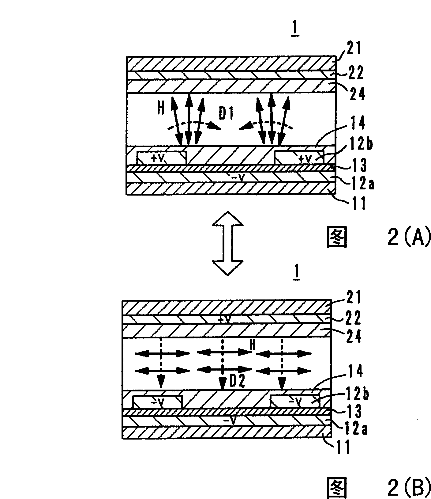
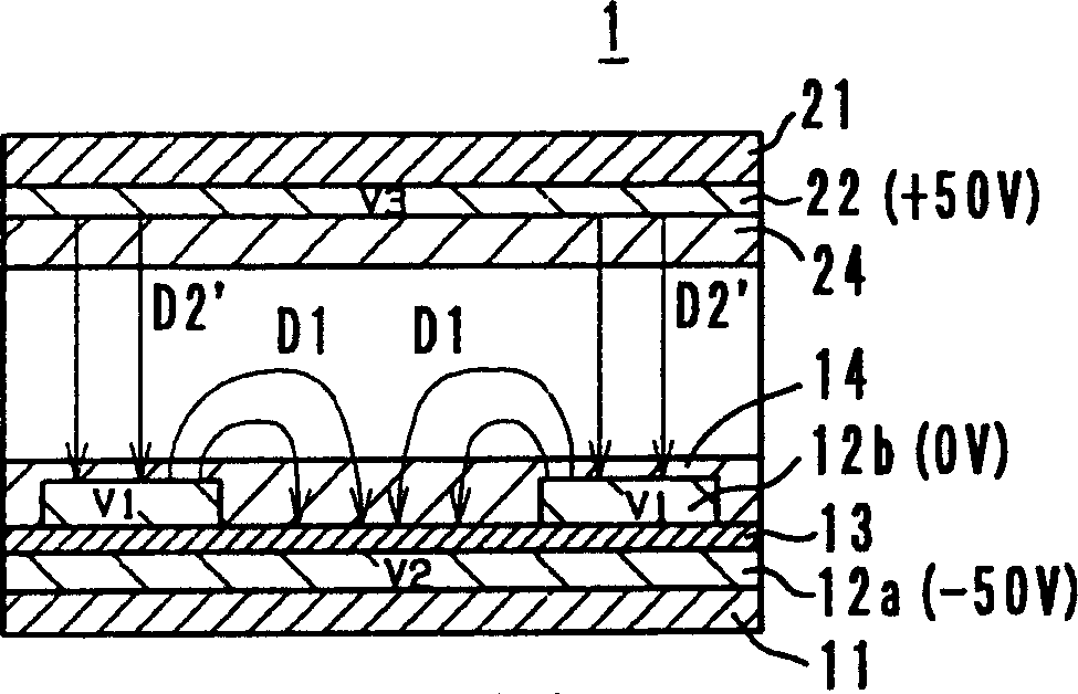
[0048] (First embodiment; see Figure 2)
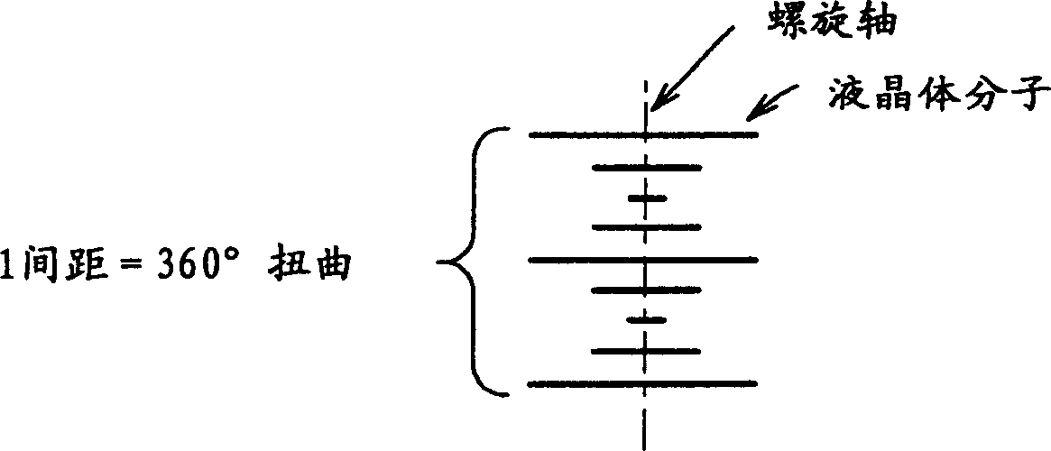
[0049] 2(A) and 2(B) show the liquid crystal display 1 of the first embodiment of the present invention. An electrode 12a, an insulating layer 13, an electrode 12b, and a reference control layer 14 are provided on the lower substrate 11. An electrode 22 and a reference control layer 24 are provided on the upper substrate 21. Between the substrates 11 and 21 is filled with chiral nematic liquid crystals, which are prepared by adding a chiral agent to the nematic liquid crystals, so that the liquid crystals exhibit bile at room temperature. Steroid phase. The part of one pixel is schematically shown in FIG. 2(A) and FIG. 2(B).
[0050] As the liquid crystal, various liquid crystals can be used as long as it exhibits a cholesteric phase at room temperature. The dielectric constant of the anisotropy of the liquid crystal can be positive or negative.
[0051] For the substrates 11 and 21, various materials can be used. Glass and plastic films s...
no. 2 example
[0077] (Second embodiment; see Figure 7-9)
[0078] Fig. 7(A) and Fig. 7(B) show a liquid crystal display 2 according to a second embodiment of the present invention. In the liquid crystal display 2, an electrode 12a, an insulating layer 13, an electrode 12b, and a reference control layer 14 are provided on the lower substrate 11. On the upper substrate 21, an electrode 22 and a reference control layer 24 are provided. Between the substrates 11 and 21, a chiral nematic liquid crystal is filled. A part of one pixel is schematically shown in FIG. 7(A) and FIG. 7(B).
[0079] The electrodes 12a and 12b are interdigital transducers, and the fingers of each interdigital transducer are so narrow that there are multiple fingers in one pixel. The fingers of the interdigital transducer extend in the same direction. Picture 9 The interdigital transducer corresponding to electrode 12a is shown. Such as Picture 9 As shown, the gasket 12a 1 Extend in the direction perpendicular to the finger...
no. 3 example
[0084] (The third embodiment; see Figure 10-12)
[0085] Fig. 10(A) and Fig. 10(B) show a liquid crystal display 3 according to a third embodiment of the present invention. An electrode 12a, an insulating layer 13, an electrode 12b, and a reference control layer 14 are provided on the lower substrate 11. An electrode 22a, an insulating layer 23, an electrode 22b, and a reference control layer 24 are provided on the upper substrate 21. The chiral nematic liquid crystal is filled between the substrates 11 and 21. In FIG. 10(A) and FIG. 10(B), only a part of one pixel is shown.
[0086] Such as Picture 11 As shown, the electrode 12a is connected to the first scan signal driving circuit 28A, and the electrode 22a is connected to the second scan signal driving circuit 28B. The electrodes 12b and 22b are connected to the data signal driving circuit 29. As shown in Figure 12 (A) and Figure 12 (B), the electrodes 12a and 22a are interdigital transducers, the structure of which has been re...
PUM
 Abstract
Description
Claims
Application Information
 - R&D
- Intellectual Property
- Life Sciences
- Materials
- Tech Scout
- Unparalleled Data Quality
- Higher Quality Content
- 60% Fewer Hallucinations
Browse by: Latest US Patents, China's latest patents, Technical Efficacy Thesaurus, Application Domain, Technology Topic, Popular Technical Reports.
© 2025 PatSnap. All rights reserved.Legal|Privacy policy|Modern Slavery Act Transparency Statement|Sitemap|About US| Contact US: help@patsnap.com