Combined drive for flur-or six-high rolling mill and operating method for the same

The technology of four-high rolling mill and six-high rolling mill is applied in the driving device of metal rolling mill, metal rolling mill stand, metal rolling stand, etc., which can solve the problems of infeasibility and achieve the effect of low cost.

Inactive Publication Date: 2003-12-10
SMS DEMAG AG
View PDF1 Cites 16 Cited by
  • Summary
  • Abstract
  • Description
  • Claims
  • Application Information

AI Technical Summary

Problems solved by technology

However, there is no provision for rapid refitting of rough rolls to the rolling mill, and such a refit is not feasible, because in the case of thicker work rolls, it is not feasible to only drive the back-up rolls and drive the work rolls by friction

Method used


Image

  • Combined drive for flur-or six-high rolling mill and operating method for the same
  • Combined drive for flur-or six-high rolling mill and operating method for the same
  • Combined drive for flur-or six-high rolling mill and operating method for the same

Examples


Embodiment Construction

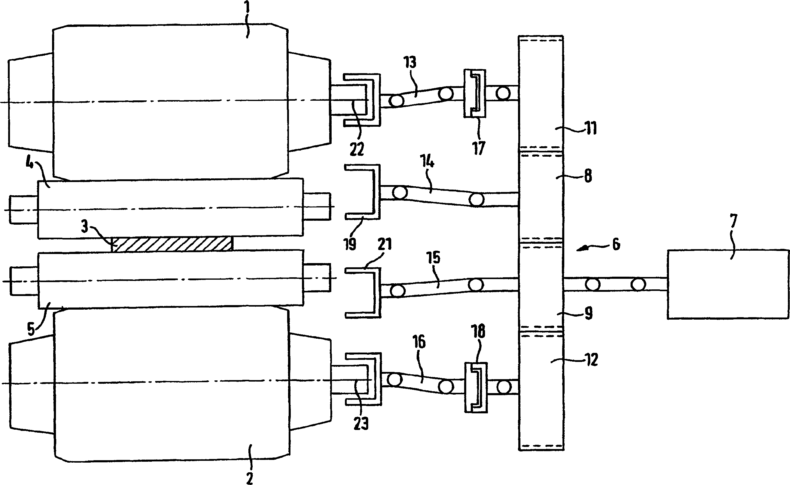
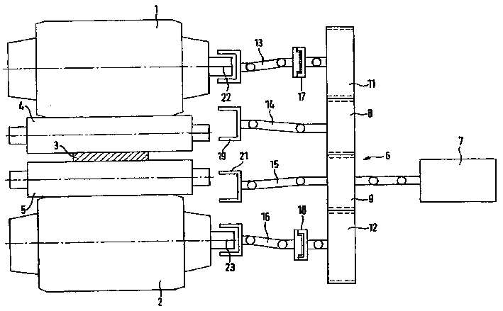
[0022] exist figure 1 , schematically shows back-up rolls 1, 2 of a four-high rolling mill, between which thin work rolls 4, 5 for a thinner rolling stock 3 are arranged.

[0023] A drive motor 7 equipped with a herringbone gear 6 is used to drive the rolls 1 , 2 , 4 , 5 . The herringbone gear transmission 6 includes two central work roll transmission gears 8 , 9 and one upper back-up roll transmission gear and one lower back-up roll transmission gear 11 , 12 .

[0024] The back-up rolls 1, 2 and the working rolls 4, 5 are respectively assigned transmission shafts 13, 14, 15, 16, and these transmission shafts are connected to the motor 7 through a herringbone gear transmission 6. The transmission shafts 13 , 16 assigned to the support rollers 1 , 2 each have an actuating clutch 17 , 18 which interrupts the force transmission path between the support rollers 1 , 2 and the electric motor 7 in the disengaged state.

[0025] because figure 1 The fine work rolls 4, 5 shown are i...


PUM


Abstract

The invention relates to a four- or six-high rolling stand for a rolling train and to a method for operating the same. The aim of the invention is to provide rolling stands that can adapt rapidly to rolling products of different thicknesses and / or hardnesses. To achieve this, rolling stands are provided with minimum expenditure that can be selectively operated with both thin and thick working rolls. The inventive combined drive in the four- or six-high rolling stand allows thick working rolls to be directly connected to a motor, whereas thin working rolls are merely carried along by neighbouring back-up rolls or intermediate rolls by means of friction.

Description

technical field [0001] The invention relates to a four-high rolling mill according to the preamble of claim 1 and a six-high rolling mill according to the preamble of claim 2 and to selectively making a four-high rolling mill or a six-high rolling mill with fine work rolls and coarse work rolls method of work. Background technique [0002] There are one or more rolling stands in a rolling mill train. In a rolling mill, the rolling stock is bitten by work rolls that rotate in opposite directions in the rolling direction. The rolled piece is advanced by the rotation of the work rolls. In the roll gap, the thickness of the rolled stock is reduced by the high pressure exerted by the work rolls. A four-high mill has two work rolls and two backup rolls. A six-high rolling mill has two work rolls, two backup rolls, and two intermediate rolls arranged between the work rolls and the backup rolls. [0003] For the rolling of very thin strips in a rolling mill train (hot strip mil...

Claims


Application Information

Patent Timeline
Patent Type & Authority Applications(China)
IPC IPC(8): B21B13/00B21B13/02B21B27/00B21B31/10B21B35/06B21B35/12B21B35/14
CPCB21B31/10B21B13/001B21B2013/025B21B35/14B21B27/00B21B35/12B21B35/06B21B2013/028
Inventor J·赛德尔G·克内佩W·沃尔佩特
Owner SMS DEMAG AG
Why Eureka
Try Eureka