Gearless permanent-magnet synchronous traction machine

A synchronous traction machine and gearless technology, which is applied in the field of elevator traction machines, can solve the problems of uneven air gap between the stator and rotor, unfavorable heat dissipation of the motor, and inability to lubricate well, and achieve compact structure, uniform air gap, good The effect of lubricity

Inactive Publication Date: 2003-12-31
SHANGHAI MITSUBISHI ELEVATOR CO LTD
View PDF1 Cites 13 Cited by
  • Summary
  • Abstract
  • Description
  • Claims
  • Application Information

AI Technical Summary

Problems solved by technology

Although the above-mentioned structure has the advantages of compactness, large torque, small loss, low noise, small vibration, stable lifting and accurate leveling, etc., the structure of the traction machine has the following defects: when the traction wheel is replaced, the rotor needs to be replaced together. If it is removed, it is easy to cause uneven air gap between the stator and the rotor; the installation of the inner closed bearing not only fails to lubricate well but also reduces the service life; the closed structure is also not conducive to the heat dissipation of the motor

Method used


Image

  • Gearless permanent-magnet synchronous traction machine
  • Gearless permanent-magnet synchronous traction machine
  • Gearless permanent-magnet synchronous traction machine

Examples


Embodiment Construction

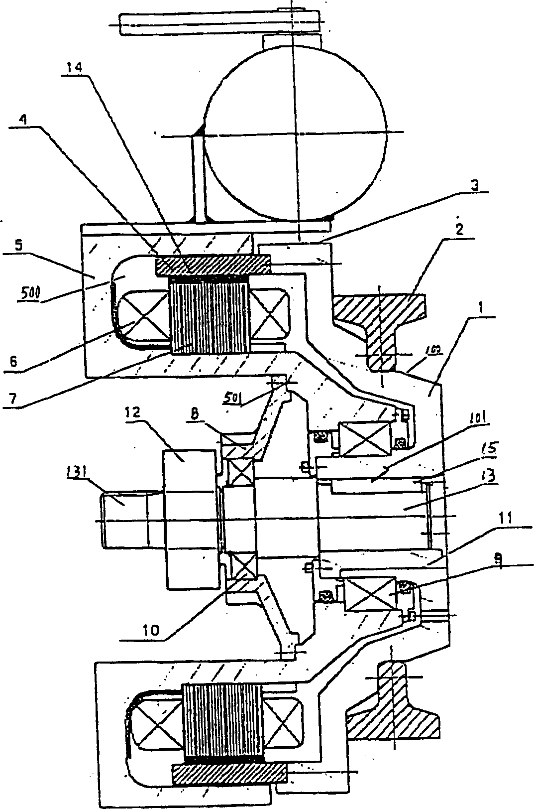
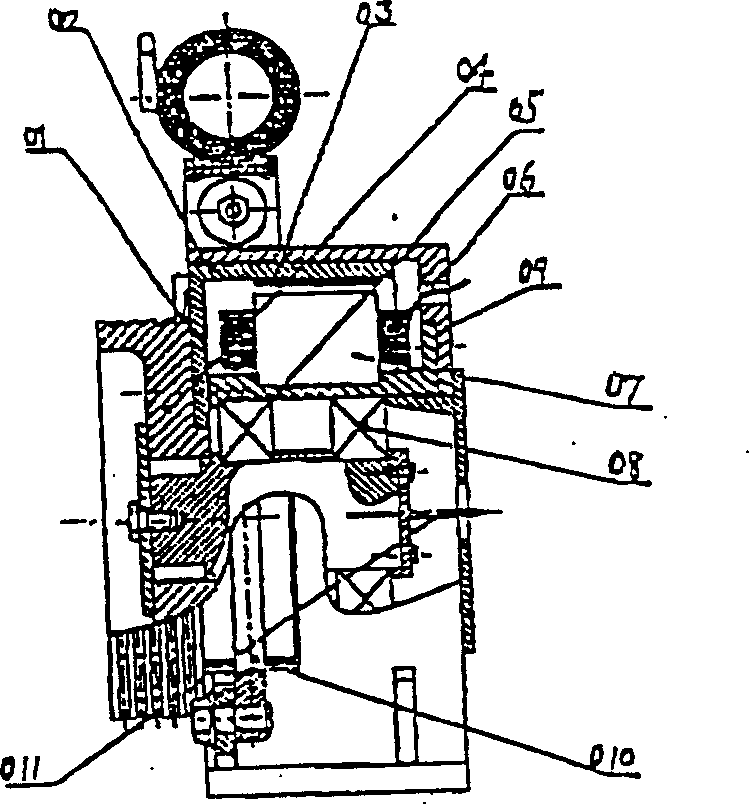
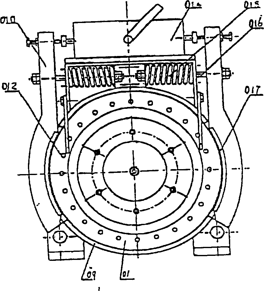
[0010] Such as figure 1 As shown, the structure of the present invention includes a bowl-shaped outer rotor 1 with a key 15 set on the hollow cylinder 101 of the main shaft 13, a traction sheave 2 is fixed on the outer surface 100 of the outer rotor 1, and a bowl mouth of the outer rotor is provided. There is a braking surface 3, and the outer circle of the hollow cylinder 101 of the outer rotor 1 is sequentially fitted with bearings 9 and in the shape of a swallow, and the wings are bent backward to form an inner hole of an open annular groove 500. The inner hole of the stator 5 has a flange 501, and the stator 5 The stator armature iron core 7 wound with the stator winding 6 is sequentially loaded into the annular groove 500, and the outer rotor 1 is equipped with a yoke 4 and a permanent magnet 14 docked with it, and the bowl edge of the hole bottom bowl 8 is connected to the stator The inner hole flange 501 of the bowl bottom hole is connected with the bearing 10 and the ...


PUM


Abstract

The invention discloses a gearless permanent magnetic synchronization traction machine comprising a bowl shape rotor mounted on the main shaft using a sleeve with built-in hollow cylinder member, a traction wheel is secured to the external surface of the external rotor, a brake surface is arranged at the bowl shape neck of the external rotor, the bearing and the stator with flange are mounted in sequence on the circumcircle of the external hollow cylinder. The stator armature cores wound with stator winding are arranged in sequence into the annular groove of the stator, a magnet yoke and the joining permanent-magnet steel are arranged on the external rotor, the inner hole flange of the stator is connected with the rim of the hole bottom bowl shape member which in turn is connected with the bearing and the main shaft.

Description

technical field [0001] The invention relates to an elevator traction machine, in particular to a gearless permanent magnet synchronous traction machine with low speed and high torque and a manual cranking device. Background technique [0002] With the development needs of the modern construction industry, in addition to low noise, high efficiency, and reliability, the elevator also requires a small machine room or machine room-less structure. [0003] In the existing technology, such as figure 2 The application number shown is 01113256.6, and the structural schematic diagram of the name is "direct drive NdFeB permanent magnet outer rotor synchronous traction machine", image 3 yes figure 2 The side view of the traction machine adopts a multi-pole outer rotor structure and a two-layer annular stator structure; the yoke 02 of the outer rotor 01 not only serves as the support of the salient pole magnetic steel 03 to form the magnetic circuit of the motor, but also serves as t...

Claims


Application Information

Patent Timeline
Patent Type & Authority Applications(China)
IPC IPC(8): H02K1/27H02K21/12
Inventor 朱思中甘靖戈方凯
Owner SHANGHAI MITSUBISHI ELEVATOR CO LTD
Why Eureka
Try Eureka