Flow guiding type exhaust check valve

An exhaust valve and check technology, applied in the field of diversion check exhaust valve, can solve the problems of inconvenient installation of the jet tube, inconvenient installation of the jet tube, and decreased function of the jet tube, and achieve good sealing and reasonable structure. , the effect of increasing exports

Inactive Publication Date: 2004-01-14
林润泉
View PDF1 Cites 8 Cited by
  • Summary
  • Abstract
  • Description
  • Claims
  • Application Information

AI Technical Summary

Problems solved by technology

The function of the jet pipe is to discharge the flue gas discharged from the residents upwards, and the negative pressure generated by the jet pipe effectively prevents the flue gas from entering the lower room, and also prevents the flue gas from directly entering the main pipe to form an air curtain. Prevent the discharge of the smoke from the lower layer. However, after the smoke discharged from the exhaust port pushes the hammer type one-way check valve, it is blocked by the valve plate, so that the effect of the jet tube is correspondingly reduced, especially the jet tube. The lower part is a streamlined part. After being blocked by the valve plate, the effect of the streamlined shape that is conducive to the upward discharge of gas is greatly reduced, and the installation of the jet tube is extremely inconvenient, especially the jet tube with an outward flange structure. It is not easy to install, so this device needs to be further improved

Method used


Image

  • Flow guiding type exhaust check valve
  • Flow guiding type exhaust check valve
  • Flow guiding type exhaust check valve

Examples


Embodiment 1

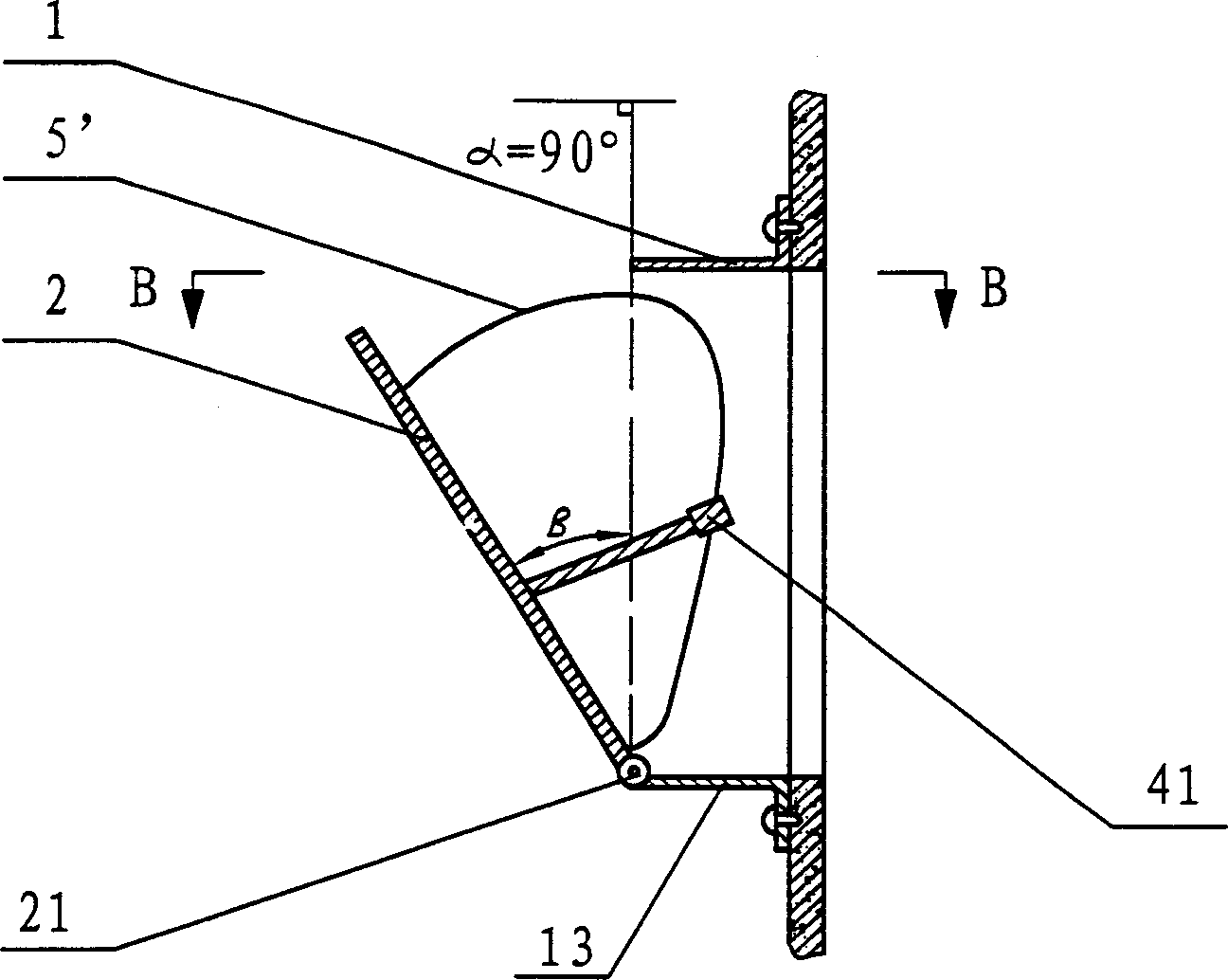
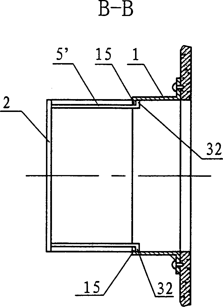
[0033] Example 1, see figure 1 , Figure A and Figure 1B , figure 1 , Figure A and Figure 1B A diversion check exhaust valve is shown in , which includes: a cylindrical valve body 1 with a rectangular cross section, a valve plate 2 and a return device, the clamp between the outlet end surface 11 of the valve body 1 and the horizontal plane The angle α is 90 degrees, the lower end of the valve plate 2 is hinged to the outlet end of the bottom surface 13 of the valve body 1 through the valve plate rotating shaft 21, and the return device fixed on the inner surface of the valve plate 2 is a weight 41. The disc 2 is within the maximum opening position, the center of gravity of the valve disc 2 and the center of gravity of the weight 41 are always on both sides of the hinge point of the valve disc shaft 21, and the gravity moment of the weight 41 on the hinge point of the rotating shaft is greater than that of the valve disc 2 on the hinge point The moment of gravity, after t...

Embodiment 2

[0034] Example 2, see figure 2 , Figure 2A with Figure 2B , figure 2 , Figure 2A with Figure 2BAnother preferred diversion check exhaust valve is shown in , which includes: a valve body 1 with a square cross section, a valve plate 2 and a return device, the outlet end of the bottom surface 13 of the valve body 1 faces The oblique upward extension is in the shape of an arc, and of course it can also extend upwards in an inclined or folded shape. The arc is the best, and the bottom ends of the two sides 14 of the valve body 1 extend together with the outlet end of the bottom surface 13, so that An inclined valve body outlet end surface 11 is formed. The angle α between the outlet end surface 11 and the horizontal plane is 45 degrees, and the lower end of the valve plate 2 is hinged to the outlet end of the bottom surface 13 of the valve body 1 through the valve plate rotating shaft 21. Figure 2A , Figure 2B Among them, the return device is a return spring 42 conne...

Embodiment 3

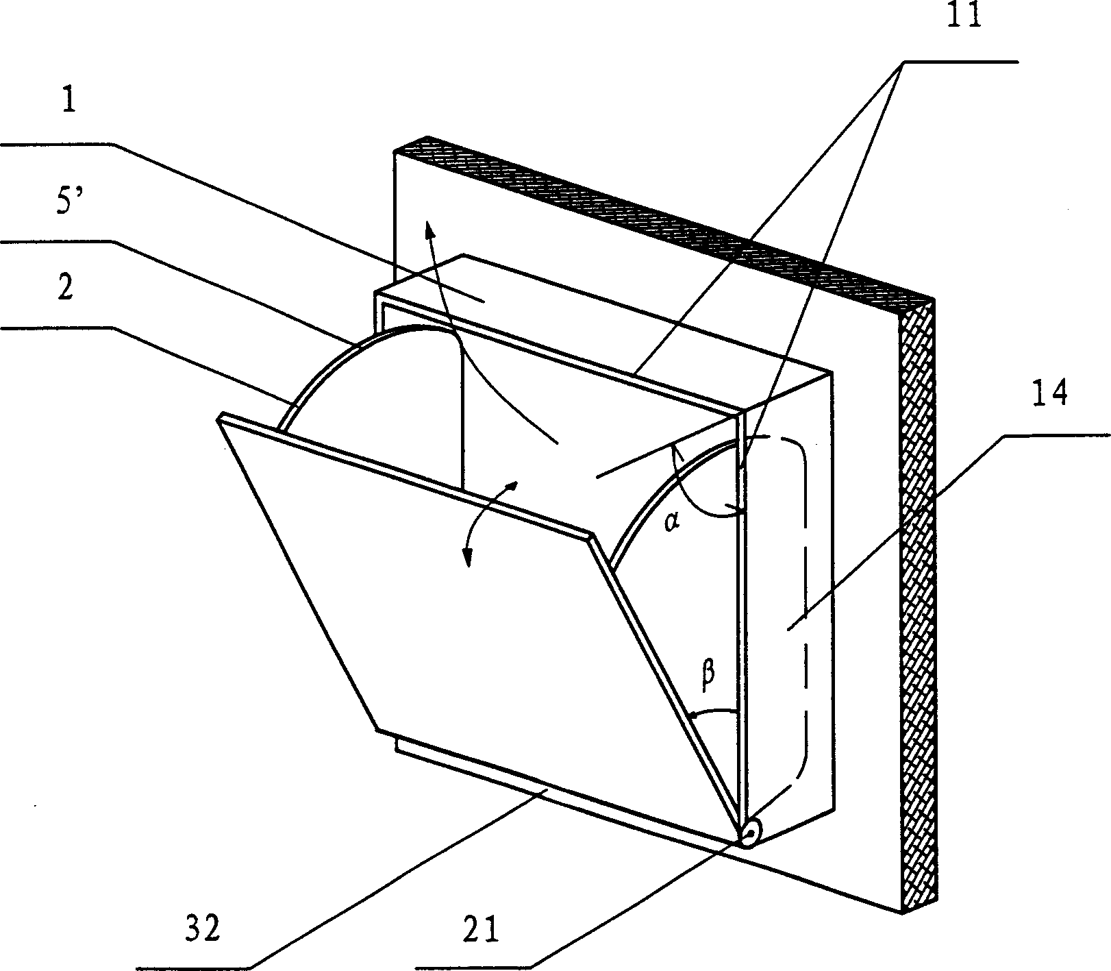
[0035] Example 3, see image 3 , image 3 shows a preferred flow diversion check exhaust valve, which includes: a valve body 1 with a square cross section, a valve plate 2 and a return device; the outlet end of the bottom surface 13 of the valve body 1 is inclined The upper part is arc-shaped, and the lower end of the valve plate 2 is hinged to the outlet end of the bottom surface 13 of the valve body 1 through the valve plate rotating shaft 21. The above-mentioned return device is connected between the valve plate 2 and the valve body 1. Return spring 42. Two guide fins are arranged on both sides of the valve sheet 2 close to the edge, and the guide fins are movable fins 5' that are perpendicular to the valve sheet 2 and fixed on both sides of the valve sheet 2. The shape of the sheet 5' is roughly fan-shaped, and the shape of the movable flap 5' is a shape capable of sealing or covering the opening between the valve sheet 2 and the side of the valve body 1 when the valve s...


PUM


Abstract

The invention relates to a non-return exhaust valve used for the concentration discharging of flue gas in the dwelling construction comprising, valve body, valve block and valve block and returning apparatus, wherein the lower end of the valve block is hinged to the exit end floor of the valve body, the returning apparatus is arranged on the valve block, two flow guiding flaps are arranged on the two sides of the valve block, a stopping means for limiting valve maximum open angle is arranged on the valve block. The invention solves the problem of the difficulty of the jet flow tube mounting, it can reduce the cost and increase the packing performance.

Description

technical field [0001] The invention relates to a one-way exhaust device, in particular to a diversion type check exhaust valve which is used in various types of residences to facilitate the smooth discharge of smoke, and effectively prevents the upper and lower floors of high-rise buildings from passing through. The problem of cross-gas in the shared exhaust pipe. technical background [0002] Now all kinds of residences use a common main exhaust pipe, and each household directly discharges the indoor smoke into the main pipe through the air inlet on the main pipe, and discharges it from the exit of the roof. Generally, the exhaust gas of each household The air pipe and the main pipe are vertically arranged, which is not conducive to the upward discharge of the smoke. The smoke entering the main pipe will form an air curtain, and at the same time will prevent the lower airflow from rising and discharging, especially when the lower airflow is affected by the resistance of th...

Claims


Application Information

Patent Timeline
Patent Type & Authority Applications(China)
IPC IPC(8): F16K15/03
Inventor 林润泉
Owner 林润泉
Why Eureka
Try Eureka